Combined use of Optical and Contact probes

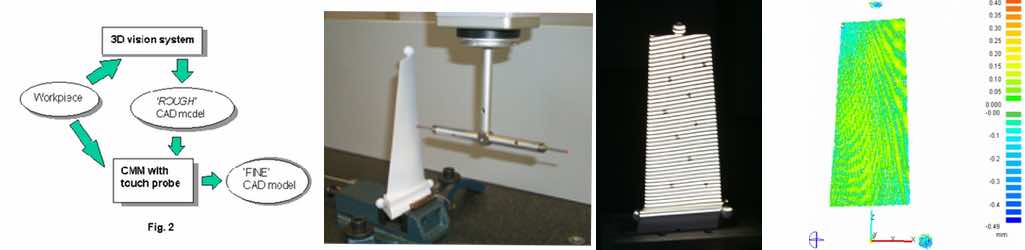
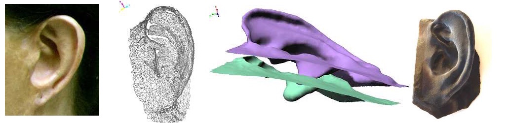
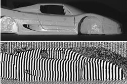
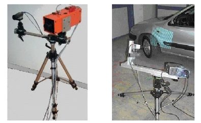
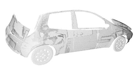
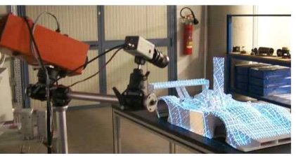
This activity was carried out in the frame of a collaboration between our Laboratory and the DIMEG Metrological Laboratory of the University of Padova. It was aimed at integrating the measurement information from a 3D Vision sensor and a Coordinate Measuring Machine (CMM) for the reverse engineering of free-form surfaces. The objective was to reconstruct the CAD model of comples shapes with high accuracy and at the same time rapidly, and minimising the operator time.

3D prosthetic applications to maxillo-facial defects

In the last years, prosthetic techniques have gained increased interest in post oncological reconstruction and in congenital defect treatment. Both the fuctional and the aesthetic characteristics of the prosthesis are crucial, in view of allowing the patient to overcome the social, psychological and economic problems deriving from their handicap.

Traditional reconstruction techniques present a number of lacks: the patient’s discomfort and stress, the inaccuracy of the replicas, and the dependence on the artistic skills of an experienced prosthetist. In addition, the mould production process is cumbersome, and time consuming. Finally, the overall process is not adaptive, i.e., whenever the existing prothesis should be replaced, the overall process must be carried out from scratch.

The purpose of this research activity is to develop a novel approach that combines optical three-dimensional acquisition, reverse engineering (RE) and rapid prototyping (RP) for the prosthetic reconstruction of facial prostheses.

Relevant Publications

Sansoni, G.; Cavagnini, G.; Docchio, F.; Gastaldi, G. “Virtual and physical prototyping by means of a 3D optical digitizer: application to facial prosthetic reconstruction“, Virtual and Physical Prototyping, Vol. 4, pp. 217-226. 2009

Sansoni, G.; Trebeschi, M.; Cavagnini, G.; Gastaldi, G. “3D Imaging acquisition, modeling and prototyping for facial defects reconstruction“, Proceedings of SPIE Three-Dimensional Imaging Metrology, Vol. 7239, pp. 1-8. 2009

Cavagnini, G.; Sansoni, G.; Vertuan, A.; Docchio, F. “3D optical Scanning: application to forensic medicine and to maxillofacial reconstruction“, Proceedings of International Conference on 3D Body Scanning Technologies, pp. 167-178. 2010

Study case: ear reconstruction

The example that we present in this article concerns the reconstruction of an ear. The approach is based on optical acquisition and modeling of the shapes. The final prosthesis is directly obtained from the model by means of rapid prototyping.

The patient’s defect is shown in the Fig. 1. The left ear is seriously damaged in consequence of a burn. To fabricate the prosthetic element, the right ear, shown in Fig. 2, was used as the template.

The test was performed as follows: first, we acquired the right, safe ear. We configured the digital scanner (Vivid 910 , Konica Minolta Inc.) in the MIDDLE configuration. Four views were acquired and aligned together. Then the triangle mesh was obtained and mirrored, in view of using it to model the prosthesis. The corresponding models are shown in Fig 3a, 3b and 3c. As a second step, the defect was gauged. The system configuration was the same as the one in the previous acquisition. Two views were sufficient to cover the whole surface. The mesh was created over the aligned views. The result is presented in Fig 3d.

The third step was the acquisition of the whole patient face in three views, as shown in Fig. 4. This model was used as the skeleton to align the mesh in Fig. 3d to the one in Fig. 3c. The model of the defect was aligned to the skeleton. Then the model of the ear was interactively aligned until the aesthetical appearance on the whole face was judged optimal. At this point, the skeleton was discarded. The two models were edited to fill residual holes and to reconstruct missing surface parts (mainly due to undercuts). Finally, they were finely connected in correspondence with their borders. The result of this step is shown in Fig. 5.

The mesh has been topologically controlled to produce the physical copy. This has been fabricated by means of rapid prototyping technology. The Connex 500 3D Printing System (Objet-Geometries Inc.) has been used. This machine is capable of printing parts and assemblies made of multiple model materials all in a single build. The materials used to fabricate the ear prosthetic element are the TangoBlackPlus Shore A85 for the area corresponding to the auricle surface, and the TangoBlackPlus Shore A27 for the areas at the borders of the ear. The ear was obtained in about one hour; the process is very cheap (the cost is in the order of 70 Euros). Fig. 6 shows the front and the back side of the final prosthesis.

Fig. 7 shows the patient’s face after the application of the prosthetic element. It is worth noting that, in this figure, the prosthesis color is not optimized yet. In fact, we wanted to check its functionality before optimizing it under the aesthetical point of view.

Fig. 7 - Patient face with prosthesis on.

In this process, patient comfort was optimal, since the acquisition step was quick, contactless and safe. The prosthesis try-in was unnecessary. The prototyping step was very cheap, and the overall time required was about six hours, plus the machining of the prosthesis.

auto_orig_e_frange.jpg

Student Projects 2006-2007

This is an example of the typical project in the course of Optical Measurements

The students have been involved into the acquisition of a small car by using the system based on the projection of structured light. The PolyWorks suite of programs was used to acquire the mesh.

The real difficulty in this project was the calibration of OPL-3D, since it requires the knowledge of calibration camera models and the experimental practice with calibration masters  and setup of the projector-camera pair.

The students are Marco Tomasini and Michele Mancini. Download the presentation to have an insight of the work.

The small car to be acquired and renderize by using OPL-3D.

This project has been carried out at the city museum (Museo di Santa Giulia), where the students had to acquire the Winged Victory of Brescia statue using the Vivid 910 Scanner as the measurement sensor.

The statue was already measured in 2001 by using OPL-3D. The aim was to compare the measurement performances when coherent light (Vivid 910) is used instead of incoherent light (OPL-3D). 

The students who carried out the project are Nicola Modonesi and Davide Barba. Here you can download a brief presentation of their work.

The beautiful Winged Victory of Brescia statue to be acquired by the students.

In this project the students had to acquire a bas-relief at the Museo di Santa Giulia of Brescia by using the Vivid 910 Scanner.

The bas-relief is a very large one, representing the patron saints of Brescia, St. Faustino and Giovita. The aim was to produce the triangle mesh of the bass-relief.

The students who carried out the project are Mauro Facchini and Emanuele Tonoli. Here you can download a brief presentation of their work.

The bas-relief of Saints Faustino and Giovita to be acquired by the students.
OPL-3D_1.jpg

OPL-3D: a portable system for point cloud acquisition

OPL-3D has been specifically designed for applications of reverse engineering and rapid prototyping, as well as for applications of measurement and quality control.

The system exploits active stereo vision (the absolute approach is implemented) using time-multiplexing based on the Gray-Code-Phase-Shifting method.

The projector-camera pair

OPL-3D can host a wide variety of projectors. In the left figure in Fig. 1 the device is the ABW LCD 320: it is a microprocessor-controlled and column-driven projector, specifically intended to be used in this class of systems. Alternatively, those devices currently available for video projection can be succesfully used, as that one shown on the right figure in Fig. 1 (Kodak DP 900, based on DLP technology).

The detector is a commercial CCD video camera. In the configurations shown in Fig. 1, the camera is an inexpensive colour Hitachi KP D50, with standard resolution (752 x 582 px). However, any type of camera (black/white or colour, with single or multiple CCDs for colour separation, and with different pixel densities) can be mounted on the system, depending on the application and on the projector used. In Fig. 2, for example, a 1300 x 1030 px digital video camera (Basler model) is mounted, to acquire at the required resolution large fields of views

The mount

The projector and the camera are mounted onto a rigid bar, that can be easily moved around the scene by means of a tripod, and that holds the adjustment units for proper orientation. The mount is fully reconfigurable: all parameters can be varied according to the distance from the target, the required measurement resolution and the FoV (Fig. 3).

Given the fact that through sophisticated calibration procedures the system is able to finely estimate the operating parameters, no accurate positioning equipment (micropositioners, microrotators) is required, the only requirement being stability of the mount during the measurement procedure.

Fig. 4 shows two examples of on-site measurements of complex shapes where the full flexibility of the system was mandatory to perform the acquisition.

Fig. 3 - Images of the tripods used and of the equipment of the prototype.
Fig. 4 - Two on-site acquisition campaigns carried out by the Laboratory: the Winged Victory point cloud acquisition (left) and the Ferrari point cloud acquisition (right).

The electronic hardware

OPL-3D is equipped with a PC, that has the purpose of (i) driving the projector with the appropriate pattern sequence, (ii) acquiring the image sequences from the target, and (iii) elaborating the images. In addition, it contains all the features to perform sophisticated procedures for setting up and reconfiguration.

The PC is in the current configuration a Pentium III 900 MHz, 1 GB Ram, equipped with a Matrox Meteor II Frame Grabber. The Projector is operated by the PC through the Serial Connector.

PERFORMANCE

OPL-3D exhibits low-measurement uncertainty (120 mm) over large measurement areas (450 x 340 mm), linearly scalable in the case of smaller areas. Special care has been devoted to flexibility of use, in-field measurement setting, reconfigurability and robustness against environmental light changes and surface colour and texture

Fig. 5 shows the acquisition of the blue car already seen in Fig. 2. Multiview alignment and registration is performed by either purposely designed software or by means of commercially available products, depending on the complexity of the process.

Fig. 5 - Point Cloud obtained with every acquisition aligned to form a complete and dense reconstruction.

Technology transfer

OPL 3-D has been put into the market by Open Technologies s.r.l., Italy, a start-up company of the University of Brescia, under the Trade Name of 3DShape, in a manifold of versions, including sophisticated software for multi-view combination, point cloud manipulation and transformation, up to surface generation.

Commercial software for Reverse Engineering

The softwares

Two commercial software suites are successfully used by the Group to carry out the reverse engineering of very complex objects. These are the Polyworks 7.0 suite and the Raindrop Geomagic Studio 3.1 suite of programs.

Polyworks is specifically designed to obtain triangle meshes from point clouds. The IM-Align module is very powerful and allows us to perform the multiview acquisition when the number of point clouds is very high (from 30 to 500). The IM-Merge, IM-Edit and IM-Compress are used to create the triangle models, depending on the level of accuracy of the original point cloud, and on the accuracy required to the polygonal mesh. The work environment allows the operator to finely adjust, smooth, fill, join, close the final model by means of a considerable number of functions.

The Geomagic environment is designed to produce, from the original point cloud, the triangle models and the NURBS models. These are obtained starting from the triangle meshes. The software privileges the automation of the whole process with respect to the fine, local adjusting of the surfaces.

In the work carried out untill now, the Polyworks Suite has been preferred when (i) the measurement targets are characterised by a high level of complexity and by the presence of small details, (ii) the acquired point clouds result into a high number of invalid points and the quality of the measurement is not optimal, and (iii) the reverse engineering process requires only the generation of triangles. This is the case of the experimental work carried out in the summer of 2001 at the Civici Musei of Brescia, dealing with the modelling of the ‘Winged Victory’.

On the other hand, the Geomagic suite is used when (i) the shapes are generally regular and are efficiently elaborated (edited, filtered, topologically controlled) in an automatic way, (ii) the process time has to be kept low, (iii) the CAD model is required. The reverse engineering of the Ferrari 250MM has been performed in spring 2002 by using this software environment.

A Reverse Engineering example

The example reported here fully documents the reverse engineering process of the object in Fig. 1 carried out by using both the mentioned software products.
It is a 1:4 scaled model of a F333 (by courtesy of Ferrari and Officine Michelotto). The following figures illustrate all the main steps of the test. These are:

  1. the optical acquisition by means of OPL-3D (Fig. 1);
  2. the alignment process to obtain the point cloud of the whole object (Fig. 2). It has been performed by using the IM-Align module;
  3. the generation of the triangle model (Fig. 3). IM-Merge has been used in this step: it allowed the creation of a number of models at different levels of detail;
  4. the generation of the CAD model (Fig. 4). It has been obtained by exporting the triangle model from the Polyworks environment to the Geomagic Environment (the STL format has been used), and by exploiting the powerful tools for the generation of the patch layout and the matematics of the surfaces available in Geomagic Studio 3.0. 

Fig. 5 shows the rendered view of the CAD model.

Fig.1 - The acquisition of the F333 by means of OPL-3D.

OptoSurfacer: an optical digitizer for reverse engineering of free-form surfaces

What is OptoSurfacer?

The purpose of this activity is the development of descriptive 3D models of the point clouds acquired by the optical digitisers developed at the Laboratory, for the implementation of the Reverse Engineering of complex shapes and in applications that priviledge the efficiency of the whole process with respect to its accuracy.

Typical fields are the production of prototypes and moulds within the collaborative design process and for copying applications, the restitution of cultural heritage, and the Virtual Reality.

The objective is also the implementation of an alternative path with respect to the traditional CAD-based process, to allow the user to model the physical shapes by means of meshes of simple geometrical elements, without requiring specialised knowledge and background, and at the same time providing total compatibility with the higher performance, higher cost, market available software environments, dedicated to CAD and copying applications.

The activity resulted in the development of a software tool called OptoSurfacer, with the following characteristics:

  1. importing and ordering of dense and sparse point clouds, optically acquired;
  2. detection and editing of undercuts and outlayers;
  3. scalingmirroring and translation of the entities;
  4. automatic definition of the meshes that model the original measurement data;
  5. flexible trimmering of the mesh topology depending on the object local curvature;
  6. coding of the models in the IGES format to guarantee their usability in the CAD and CAM environments market available.

HOW TO OBTAIN THE MESHES?

The flow-chart in Fig. 1 describes the tasks performed by OptoSurfacer. They are illustrated for the study case of the object shown in Fig. 2 (a roof tile). The corresponding point cloud, shown in Fig. 3 has been acquired by means of the prototype DFGM (see the Prototypes page), and is characterised by a variability of the measurement of about 200 microns.

Fig. 3 - Corresponding point cloud of the roof tile obtained by means of the prototype DFGM.

OptoSurfacer automatically performs the ordering of the points by creating a regular reference grid and by using the surface shown in Fig. 4 as the basic geometrical element of the mesh. For the roof tile, the shapes have been modelled as shown in Fig. 5, and the resulting mesh is presented in Fig. 6. The irregularities well observable in this figure mainly depend on the roughness and the porosity of the material.

Fig. 4 - Basic geometrical element of the mesh.
Fig. 5 - Reference model to model the roof tile.
Fig. 6 - Resulting mesh of the roof tile obtained.

The solid model of the object has been obtained from the mesh representation of Fig. 6. OptoSurfacer generated the sections presented in Fig. 7 and, by blending them, the mathematics of the object. The final solid model is shown in Fig. 8: it is saved in the IGES format, and presents full compatibility with a wide number of CAD-CAM products market available.

Relevant Publications

Sansoni, G.; Docchio, F. “In-field performance of an optical digitizer for the reverse engineering of free-form surfaces“, The International Journal of Advanced Manufacturing Technology, Vol. 26, no. 11–12, pp. 1353–1361. 2005