3D prosthetic applications to maxillo-facial defects

In the last years, prosthetic techniques have gained increased interest in post oncological reconstruction and in congenital defect treatment. Both the fuctional and the aesthetic characteristics of the prosthesis are crucial, in view of allowing the patient to overcome the social, psychological and economic problems deriving from their handicap.

Traditional reconstruction techniques present a number of lacks: the patient’s discomfort and stress, the inaccuracy of the replicas, and the dependence on the artistic skills of an experienced prosthetist. In addition, the mould production process is cumbersome, and time consuming. Finally, the overall process is not adaptive, i.e., whenever the existing prothesis should be replaced, the overall process must be carried out from scratch.

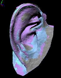
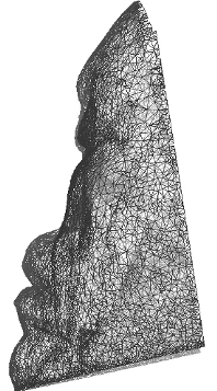
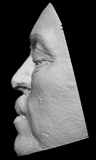
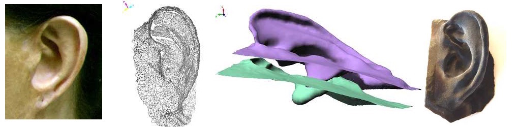
The purpose of this research activity is to develop a novel approach that combines optical three-dimensional acquisition, reverse engineering (RE) and rapid prototyping (RP) for the prosthetic reconstruction of facial prostheses.

Relevant Publications

Sansoni, G.; Cavagnini, G.; Docchio, F.; Gastaldi, G. “Virtual and physical prototyping by means of a 3D optical digitizer: application to facial prosthetic reconstruction“, Virtual and Physical Prototyping, Vol. 4, pp. 217-226. 2009

Sansoni, G.; Trebeschi, M.; Cavagnini, G.; Gastaldi, G. “3D Imaging acquisition, modeling and prototyping for facial defects reconstruction“, Proceedings of SPIE Three-Dimensional Imaging Metrology, Vol. 7239, pp. 1-8. 2009

Cavagnini, G.; Sansoni, G.; Vertuan, A.; Docchio, F. “3D optical Scanning: application to forensic medicine and to maxillofacial reconstruction“, Proceedings of International Conference on 3D Body Scanning Technologies, pp. 167-178. 2010

Study case: ear reconstruction

The example that we present in this article concerns the reconstruction of an ear. The approach is based on optical acquisition and modeling of the shapes. The final prosthesis is directly obtained from the model by means of rapid prototyping.

The patient’s defect is shown in the Fig. 1. The left ear is seriously damaged in consequence of a burn. To fabricate the prosthetic element, the right ear, shown in Fig. 2, was used as the template.

The test was performed as follows: first, we acquired the right, safe ear. We configured the digital scanner (Vivid 910 , Konica Minolta Inc.) in the MIDDLE configuration. Four views were acquired and aligned together. Then the triangle mesh was obtained and mirrored, in view of using it to model the prosthesis. The corresponding models are shown in Fig 3a, 3b and 3c. As a second step, the defect was gauged. The system configuration was the same as the one in the previous acquisition. Two views were sufficient to cover the whole surface. The mesh was created over the aligned views. The result is presented in Fig 3d.

The third step was the acquisition of the whole patient face in three views, as shown in Fig. 4. This model was used as the skeleton to align the mesh in Fig. 3d to the one in Fig. 3c. The model of the defect was aligned to the skeleton. Then the model of the ear was interactively aligned until the aesthetical appearance on the whole face was judged optimal. At this point, the skeleton was discarded. The two models were edited to fill residual holes and to reconstruct missing surface parts (mainly due to undercuts). Finally, they were finely connected in correspondence with their borders. The result of this step is shown in Fig. 5.

The mesh has been topologically controlled to produce the physical copy. This has been fabricated by means of rapid prototyping technology. The Connex 500 3D Printing System (Objet-Geometries Inc.) has been used. This machine is capable of printing parts and assemblies made of multiple model materials all in a single build. The materials used to fabricate the ear prosthetic element are the TangoBlackPlus Shore A85 for the area corresponding to the auricle surface, and the TangoBlackPlus Shore A27 for the areas at the borders of the ear. The ear was obtained in about one hour; the process is very cheap (the cost is in the order of 70 Euros). Fig. 6 shows the front and the back side of the final prosthesis.

Fig. 7 shows the patient’s face after the application of the prosthetic element. It is worth noting that, in this figure, the prosthesis color is not optimized yet. In fact, we wanted to check its functionality before optimizing it under the aesthetical point of view.

Fig. 7 - Patient face with prosthesis on.

In this process, patient comfort was optimal, since the acquisition step was quick, contactless and safe. The prosthesis try-in was unnecessary. The prototyping step was very cheap, and the overall time required was about six hours, plus the machining of the prosthesis.

Study case: nose reconstruction

In this page, the application of the method to the case of nasal prosthetic reconstruction is shown. The patient suffered from a total loss of the nose, because of excision of a tumor. The optical 3D laser stripe digitizer Konica Minolta Vivid 910 was used to perform data acquisition. The system was mounted on a tripod and properly oriented to optimize the acquisition view point, as shown in Fig. 1. The whole face was scanned by a eye-safe laser stripe in 0.3 seconds. The corresponding point cloud is shown in Fig. 2.

By means of suitable tessellation, the raw 3D data point were replaced by triangle tessels that maintained the information about the contiguity of the points. The polygon mesh is shown in Fig. 3. A 4 mm thickness was then internally added. The mesh was then saved in a 9 MB STL file, for subsequent prototyping.

The “sculpured model” of the patient’s face was created. To this aim, a number of healthy “donors” were engaged. The Minolta digitizer was used to acquire at the best resolution the point cloud of their nose. Each mesh was dragged and roughly matched to the reference model, to visually appreciate the appearance of the whole face, and to select the most appealing shape, under the aesthetical point of view. After it was selected, it was carefully positioned onto the reference model. The boundaries were refined and finely blended to the deformity site, to optimize the functionality and the proportions of the prosthesis. The resulting sculpured model is shown in Fig. 4. A 4 mm thickness was externally added, the mesh was then saved in a 11.3 MB STL file.

Then, the physical models were created. Both the STL files were sent through the internet for the RP machining. They were fabricated using the epoxy photo-polymerizing resinSomos Watershed 11120” by the SLA 3500 Prototyping Machine. The RP production was accomplished in about 14 hours. The two physical models are shown in Fig. 5.

The last step was the fabrication of the prosthesis. The conventional wax positive pattern was cast. To perform this task, the two physical models were physically overlapped one to the other and the wax was poured as shown in Fig. 6. The wax pattern was then positioned on the prototype of the reference model as shown in Fig. 7. In this way, it was possible to perform the try-in of the prosthesis and its refinement on this copy, without disturbing the patient. The definitive prosthesis was obtained by conventional flasking and investing procedures. Fig. 8 shows the patient after the positioning of the prosthesis. It was then manually refined on the patient’s face, to match the skin color and texture. This operation was possible thanks to the collaboration with the medical team of the Faculty of Medicine of the University of Brescia and the precious contribution of Dr. Vincenzo Cavallari, technical specialist in facial and dental implants.