
Laboratorio di Misure Meccaniche e Termiche
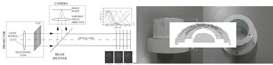
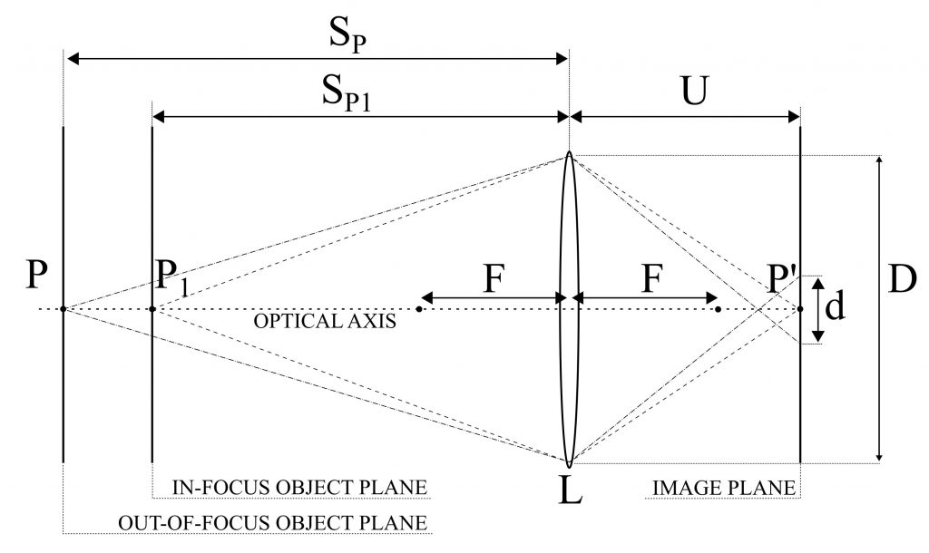
A novel Depth From Defocus (DFD) measurement system is has been developed. Here the extension of the measurement range is performed using an emergent technology based on liquid lenses. A suitable set of different focal lengths, obtained by properly changing the liquid lens supply voltage, provides multiple camera settings without duplicating the system elements or using moving parts.
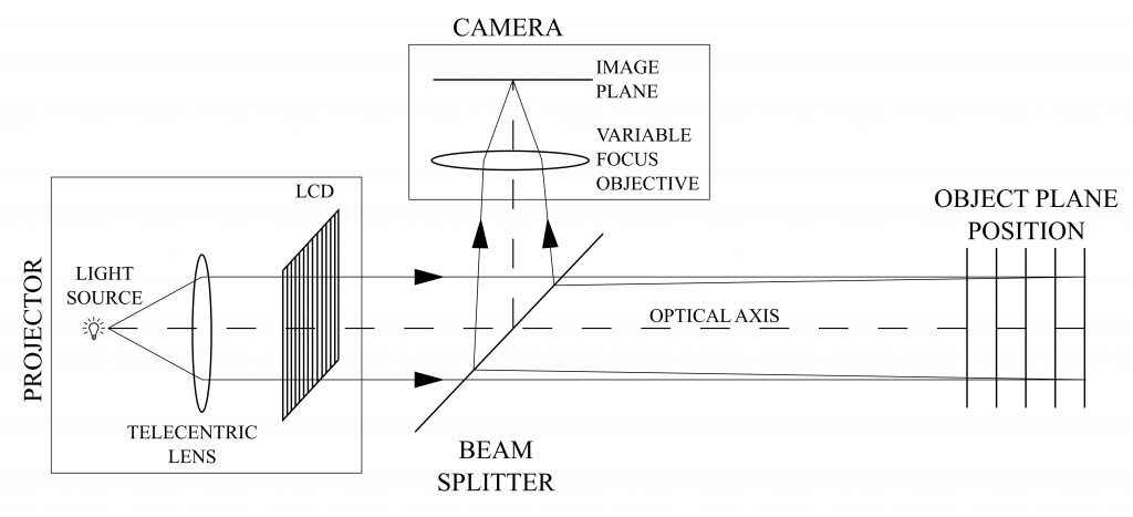
A simple and compact setup, with a single camera/illuminator coaxial assembly is obtained. The measurement is based on an active DFD technique using modulation measurement profilometry(MMP) for the estimation of the contrast at each image point as a function of the depth range.
A suitable combination of multiple contrast curves, each one derived at a specific focal length, is proposed to extend the measurement range and to improve the measurement performances with respect to the state of the art.
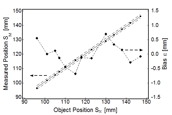
The system measurement errors are 0.53 mm over an extended measurement depth range of 135 mm, corresponding to 0.39 % of the depth range, resulting in an improved performance with respect to the state of the art DFD systems, for which typical values are in the 0.7-1.6 % of the depth range.
Pasinetti, S.; Bodini, I.; Lancini, M.; Docchio, F.; Sansoni, G. “A Depth From Defocus Measurement System Using a Liquid Lens Objective for Extended Depth Range“, IEEE Transactions on Instrumentation and Measurement, Vol 66, no. 3, pp. 441-450. 2017
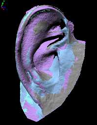
The example that we present in this article concerns the reconstruction of an ear. The approach is based on optical acquisition and modeling of the shapes. The final prosthesis is directly obtained from the model by means of rapid prototyping.
The patient’s defect is shown in the Fig. 1. The left ear is seriously damaged in consequence of a burn. To fabricate the prosthetic element, the right ear, shown in Fig. 2, was used as the template.
The test was performed as follows: first, we acquired the right, safe ear. We configured the digital scanner (Vivid 910 , Konica Minolta Inc.) in the MIDDLE configuration. Four views were acquired and aligned together. Then the triangle mesh was obtained and mirrored, in view of using it to model the prosthesis. The corresponding models are shown in Fig 3a, 3b and 3c. As a second step, the defect was gauged. The system configuration was the same as the one in the previous acquisition. Two views were sufficient to cover the whole surface. The mesh was created over the aligned views. The result is presented in Fig 3d.
The third step was the acquisition of the whole patient face in three views, as shown in Fig. 4. This model was used as the skeleton to align the mesh in Fig. 3d to the one in Fig. 3c. The model of the defect was aligned to the skeleton. Then the model of the ear was interactively aligned until the aesthetical appearance on the whole face was judged optimal. At this point, the skeleton was discarded. The two models were edited to fill residual holes and to reconstruct missing surface parts (mainly due to undercuts). Finally, they were finely connected in correspondence with their borders. The result of this step is shown in Fig. 5.
The mesh has been topologically controlled to produce the physical copy. This has been fabricated by means of rapid prototyping technology. The Connex 500 3D Printing System (Objet-Geometries Inc.) has been used. This machine is capable of printing parts and assemblies made of multiple model materials all in a single build. The materials used to fabricate the ear prosthetic element are the TangoBlackPlus Shore A85 for the area corresponding to the auricle surface, and the TangoBlackPlus Shore A27 for the areas at the borders of the ear. The ear was obtained in about one hour; the process is very cheap (the cost is in the order of 70 Euros). Fig. 6 shows the front and the back side of the final prosthesis.

Fig. 7 shows the patient’s face after the application of the prosthetic element. It is worth noting that, in this figure, the prosthesis color is not optimized yet. In fact, we wanted to check its functionality before optimizing it under the aesthetical point of view.
In this process, patient comfort was optimal, since the acquisition step was quick, contactless and safe. The prosthesis try-in was unnecessary. The prototyping step was very cheap, and the overall time required was about six hours, plus the machining of the prosthesis.
Copyright © 2024 MMTLab | Powered by Specia WordPress Theme