Student Projects 2014-2015

The article presents a list of projects developed for the course of 2D Vision Systems during the year 2014-2015.

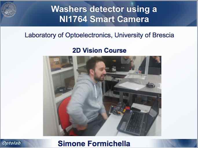
The first project was developed by Simone Formichella, with the aim of developing a small vision system to detect objects on a rotating table using a NI1764 smart camera.

One of the problems the student faced was how to detect reflective objects with optical sensors and how to deal with the transparency of the rotating plate. Moreover, the smart camera was able to perform only lightweight elaborations, so the system had to be splitted between camera and the host PC, which was able to perform the more computational heavy processing required. The whole system was developed using LabView.

The second project was developed by Alessandro Nastro, with the aim of using a very low cost projector to project fringes for 3D reconstruction. 

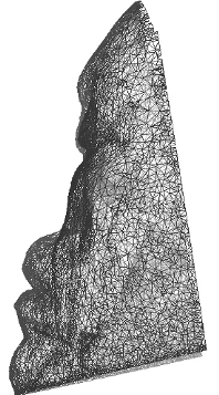
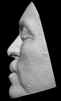
The student created a triangulation system with two Basler Scout scA1390 cameras and a low cost projector (Philips PicoPix PPX22505). The student dealt with the camera 2D calibration performed by a custom made VI developed in LabView in order to correctly detect the fringes projected on the image and retrieve the period between them. In this way it is possibile to perform a 3D reconstruction of an object!

The third project was developed by Pietro Craighero with the aim of measuring the inner and the outer radius of a mechanical object using telecentric lenses.

Telecentric lenses allow users to obtain images with high contrast with almost no image distorsion, thus being a fundamental piece of any high accuracy vision system. The student created a small set-up with a red-light laser and a telecentric camera, used to acquire 2D images of the object to be measured. The software used for the project was developed in LabView.

Combined use of Optical and Contact probes

This activity was carried out in the frame of a collaboration between our Laboratory and the DIMEG Metrological Laboratory of the University of Padova. It was aimed at integrating the measurement information from a 3D Vision sensor and a Coordinate Measuring Machine (CMM) for the reverse engineering of free-form surfaces. The objective was to reconstruct the CAD model of comples shapes with high accuracy and at the same time rapidly, and minimising the operator time.

3D image acquisition of crime scenes for documentation, analysis and medical inspection

In this thesis project the two students involved (Marco Scalvenzi and Gianluca Cavagnini) had the opportunity of using the Vivid 910 laser scanner to document 3D crime scenes at different resolution levels.

It was really interesting to capture medium range details, such as the injury tools and body parts, as well as short range details, like bullet holes, skin lesions, and blood patterns.

A numer of experiences have been performed both in indoor and in outdoor environments. The flexibility, the portability and the ease of use of this system revealed very precious to complete the projects.

ferrari_punti.jpg

To learn more on 3D Vision applications in the automotive industry

The work performed on the Ferrari presents a number of similarities with respect to the work performed on the Winged Victory: it included the 3D optical digitization of the car, and the generation of a number of polygonal and CAD models.

Fig. 1 shows a view of the whole point cloud obtained by aligning and merging 280 partial point clouds. The step has been performed with the help of suitable markers placed on the surface, given the dramatic regularity of the shapes, and the need to keep the alignment error as lower as possible. Moreover, a skeleton of few, large views (550 x 480 mm), with height resolution of 0.2 mm and measurement variability of 0.1 mm has been obtained in the first step. Then, smaller views (370 x 300 mm), with resolution of 0.1 mm and measurement error of 0.06 mm, have been acquired and merged together using the skeleton as the reference.

Fig. 1 - Complete point cloud obtained after the alignment of the different views.
The multi-view alignment and the creation of the triangle model at high resolution have been performed by using the PolyWorks software. Then, the mesh has been saved in the STL format and imported into the Raindrop Geomagic Studio environment. Here, the triangles have been edited, topologically checked, and decimated at different levels of compression, mainly using only the automatic tools embedded in the software. Fig. 2 shows one of the most dense models obtained (1.5 million of triangles), while Fig. 3 depicts the model obtained after the compression of the previous one down to 10.000 triangles: despite the high compression here applied, the model presents a high level of adherence to the original measured data, thanks to the overall “smoothness” of the car surface.
Fig. 2 - Dense model obtained by the point cloud.

As the last step, the CAD model has been created starting from the triangle mesh of Fig. 2, with minimum intervention of the operator. Fig. 4 shows the rendering of this model (the IGES format is used, resulting in a 120 MB file). The prototype of the car has been obtained at the Laboratory of Fast Prototyping of the University of Udine. The process involved the stereo lithography technique. Similarly to the prototyping of the head of the Winged Victory it resulted into the 1:10 scaled reproduction shown in Fig. 5.

retro_ferrari.jpg
Fig. 4 - CAD model obtained rendered by the software.
prototipo_ferrari.jpg
Fig. 5 - The prototype obtained by fast prototyping. Dimension: 370 x 150 x 90 mm; Material: CIBATOOL SL 5190.

Study case: nose reconstruction

In this page, the application of the method to the case of nasal prosthetic reconstruction is shown. The patient suffered from a total loss of the nose, because of excision of a tumor. The optical 3D laser stripe digitizer Konica Minolta Vivid 910 was used to perform data acquisition. The system was mounted on a tripod and properly oriented to optimize the acquisition view point, as shown in Fig. 1. The whole face was scanned by a eye-safe laser stripe in 0.3 seconds. The corresponding point cloud is shown in Fig. 2.

By means of suitable tessellation, the raw 3D data point were replaced by triangle tessels that maintained the information about the contiguity of the points. The polygon mesh is shown in Fig. 3. A 4 mm thickness was then internally added. The mesh was then saved in a 9 MB STL file, for subsequent prototyping.

The “sculpured model” of the patient’s face was created. To this aim, a number of healthy “donors” were engaged. The Minolta digitizer was used to acquire at the best resolution the point cloud of their nose. Each mesh was dragged and roughly matched to the reference model, to visually appreciate the appearance of the whole face, and to select the most appealing shape, under the aesthetical point of view. After it was selected, it was carefully positioned onto the reference model. The boundaries were refined and finely blended to the deformity site, to optimize the functionality and the proportions of the prosthesis. The resulting sculpured model is shown in Fig. 4. A 4 mm thickness was externally added, the mesh was then saved in a 11.3 MB STL file.

Then, the physical models were created. Both the STL files were sent through the internet for the RP machining. They were fabricated using the epoxy photo-polymerizing resinSomos Watershed 11120” by the SLA 3500 Prototyping Machine. The RP production was accomplished in about 14 hours. The two physical models are shown in Fig. 5.

The last step was the fabrication of the prosthesis. The conventional wax positive pattern was cast. To perform this task, the two physical models were physically overlapped one to the other and the wax was poured as shown in Fig. 6. The wax pattern was then positioned on the prototype of the reference model as shown in Fig. 7. In this way, it was possible to perform the try-in of the prosthesis and its refinement on this copy, without disturbing the patient. The definitive prosthesis was obtained by conventional flasking and investing procedures. Fig. 8 shows the patient after the positioning of the prosthesis. It was then manually refined on the patient’s face, to match the skin color and texture. This operation was possible thanks to the collaboration with the medical team of the Faculty of Medicine of the University of Brescia and the precious contribution of Dr. Vincenzo Cavallari, technical specialist in facial and dental implants.