With the Industry 4.0 paradigm, the industrial world has faced a technological revolution. Manufacturing environments in particular are required to be smart and integrate automatic processes and robots in the production plant. To achieve this smart manufacturing it is necessary to re-think the production process in order to create a true collaboration between human operators and robots. Robotic cells usually have safety cages in order to protect the operators from any harm that a direct contact can produce, thus limiting the interaction between the two. Only collaborative robots can really collaborate in the same workspace as humans without risks, due to their proper design. They pose another problem, though: in order to not harm human safety, they must operate at low velocities and forces, hence their operations are slow and quite comparable to the ones a human operator does. In practice, collaborative robots hardly have a place in a real industrial environment with high production rates.
In this context, this thesis work presents an innovative command system to be used in a collaborative workstation, in order to work alongside robots in a more natural and straightforward way for humans, thus reducing the time to properly command the robot on the fly. Recent techniques of Computer Vision, Image Processing and Deep Learning are used to create the intelligence behind the system, which is in charge of properly recognize the gestures performed by the operator in real-time.
Step 1: Creation of the gesture recognition system
A number of suitable algorithms and models are available in the literature for this purpose. An Object Detector in particular has been chosen for the job, called “Faster Region Proposal Convolutional Neural Network“, or Faster R-CNN, developed in MATLAB.
Object Detectors are especially suited for the task of gesture recognition because they are capable to (i) find the objects in the image and (ii) classify them, thus recognizing which objects they are. Figure 1 shows this concept: the object “number three” is showed in the figure, which the algorithm has to find.
Fig. 1 - The process undergone by Object Detectors in general. Two networks elaborate the image in different steps: first the region proposals are extracted, which are the positions of object of interest found. Then, the proposals are evaluated by the classification network, which at the end outputs both the position of the object (the bounding box) and the name of the object class.
After a careful selection of gestures, purposely acquired by means of different mobile phones, and a preliminary study to understand if the model was able to differentiate between left and right hand and at the same time between the palm and the back of the hand, the final gestures proposed and their meaning in the control system are showed in Fig. 2.
Fig. 2 - Definitive gesture commands used in the command system.
Step 2: creation of the command system
The proposed command system is structured as in Fig. 3: the images are acquired in real-time by a Kinect v2 camera connected to the master PC and elaborated in MATLAB in order to obtain the gesture commands frame by frame. The commands are then sent to the ROS node in charge of translating the numerical command into an operation for the robot. It is the ROS node, by means of a purposely developed driver for the robot used, that sends the movement positions to the robot controller. Finally, the robot receives the ROS packets of the desired trajectory and executes the movements. Fig. 4 shows how the data are sent to the robot.
Fig. 3 - Overview of the complete system, composed of the acquisition system, the elaboration system and the actuator system.
Fig. 4 - The data are sent to the "PUB_Joint" ROS topic, elaborated by the Robox Driver which uses ROS Industrial and finally sent to the controller to move the robot.
Four modalities have been developed for the interface, by means of a State Machine developed in MATLAB:
Points definition state
Collaborative operation state
Loop operation state
Jog state
Below you can see the initialization of the system, in order to address correctly the light conditions of the working area and the areas where the hands will probably be found, according to barycenter calibration performed by the initialization procedure.
If you are interested in the project, download the presentation by clicking the button below. The thesis document is also available on request.
Smart tracking systems are nowadays a necessity in different fields, especially the industrial one. A very interesting and successful open source software has been developed by the University of Padua, called OpenPTrack. The software, based on ROS (Robotic Operative System), is capable to keep track of humans in the scene, leveraging well known tracking algorithms that use point cloud 3D information, and also objects, leveraging the colour information as well.
Amazed by the capabilites of the software, we decided to study its performances further. This is the aim of this thesis project: to carefully characterize the measurment performances of OpenPTrack both of humans and objects, by using a set of Kinect v2 sensor.
Step 1: Calibration of the sensors
It is of utmost importance to correctly calibrate the sensors when performing a multi-sensor acquisition.
Two types of calibration are necessary: (i) the intrinsic calibration, to align the colour (or grayscale/IR like in the case of OpenPTrack) information acquired to the depth information (Fig. 1) and (ii) the extrinsic calibration, to align the different views obtained by the different cameras to a common reference system (Fig. 2).
The software provides the suitable tools to perform these steps, and also provides a tool to further refine the extrinsic calibration obtained (Fig. 3). In this case, a human operator has to walk around the scene: its trajectory is then acquired by every sensor and at the end of this registration the procedure aligns the trajectories in a more precise way.
Each of these calibration processes is completely automatic and performed by the software.
Fig. 1 - Examples of intrinsic calibration images. (a) RGB hd image, (b) IR image, (c) syncronized calibration of RGB and IR streams.
Fig. 2 - Scheme of an extrinsic calibration procedure. The second camera K2 must be referred to the first on K1, finally the two must be referred to an absolute reference system called Wd.
Fig. 3 - Examples of the calibration refinement. (a) Trajectories obtained by two Kinect not refined, (b) trajectories correctly aligned after the refinement procedure.
Step 2: Definition of measurment area
Two Kinect v2 were used for the project, mounted on tripods and placed in order to acquire the larger FoV possible (Fig. 4). A total of 31 positions were defined in the area: these are the spots where the targets to be measured have been placed in the two experiments, in order to cover all the FoV available. Note that not every spot lies in a region acquired by both Kinects, and that there are 3 performance regions highlighted in the figure: the overall most performing one (light green) and the single camera most performing ones, where only one camera (the one that is closer) sees the target with a good performance.
Fig. 4 - FoV acquired by the two Kinects. The numbers represent the different acquisition positions (31 in total) where the targets where placed in order to perform a stable acquisition and characterization of the measurment.
Step 3: Evaluation of Human Detection Algorithms
To evaluate the detection algorithms of OpenPTrack it has been used a mannequin placed firmly on the different spots as the measuring target. Its orientation is different for every acquisition (N, S, W, E) in order to better understand if the algorithm is able to correctly detect the barycenter of the mannequin even if it is rotated (Fig. 5).
The performances were evaluated using 4 parameters:
MOTA (Multiple Object Tracking Accuracy), to measure if the algorithm was able to detect the human in the scene;
MOTP (Multiple Object Tracking Precision), to measure the accuracy of the barycenter estimation relative to the human figure;
(Ex, Ey, Ez), the mean error between the estimation of the barycenter position and the reference barycenter position known, relative to every spatial dimension (x, y, z);
(Sx, Sy, Sz), the errors variability to measure the repetibility of the measurments for every spatial dimension (x, y, z).
Fig. 5 - Different orientations of the mannequin in the same spot.
Step 4: Evaluation of Object Detection algorithms
A different target has been used to evaluate the performances of Object Detection algorithms, shown in Fig. 6: it is a structure on which three spheres have been positioned on top of three rigid arms. The spheres are of different colours (R, G, B), to estimate how much the algorithm is colour-dependant, and different dimensions (200 mm, 160 mm, 100 mm), to estimante how much the algorithm is dimension-dependant. In this case, to estimate the performances of the algorithm the relative position between the spheres has been used as the reference measure (Fig. 7).
The performances were evaluated using the same parameters used for the Human Detection algorithm, but referred to the tracked object instead.
Fig. 6 - The different targets: in the first three images the spheres are of different colours but same dimension (200 mm, 160 mm and 100 mm), while in the last figure the sphere where all of the same colour (green) but of different dimensions.
Fig. 7 - Example of the reference positions of the spheres used.
If you want to know more about the project and the results obtained, please download the master thesis below.
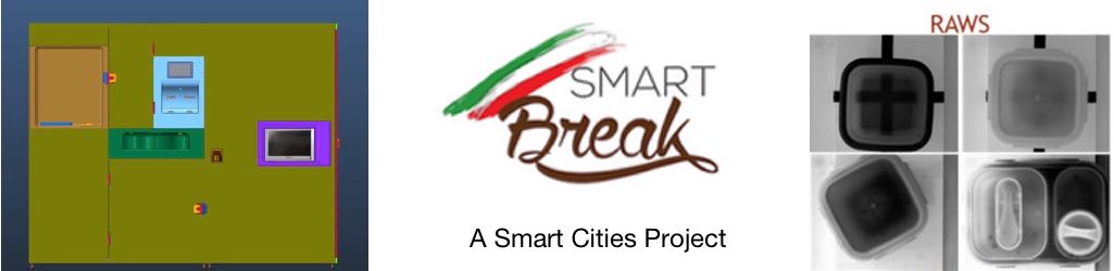
SMART BREAK is a project funded by Regione Lombardia thanks to a grant in the field of “Smart cities and communities”, for ambient assisted living. Nine companies (Bialetti Industrie Spa, Connexxalife Srl, Elemaster Spa, Lampia Srl, Gualtiero Marchesi Srl, Synergie CAD Instruments Srl, SAEF Srl, Sait Srl, and Signal Srl), two universities (UniBS and UniBG) and one hospital (San Raffaele) have joined the SMART BREAK project, and Bialetti Industrie is the leading partner.
SMART BREAK will be a modular system: food will be heated, hot and cold drinks will be provided as well as smoothies and users will be profiled, to create a food diary.
The Laboratory contributes to the project and works on a vision system, based on a smart camera (VisionCam XS – Imago Technologies), which communicates by means of an HMI, via a Modbus Ethernet Protocol. The developed vision system is capable of reading EAN barcodes, for the food diary and of recognizing lunch boxes of known weight.
The machine under development. Ileana is working at the vision system.
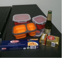
Food containers and barcodes that have to be recognized.
The article presents a list of projects developed for the course of 2D Vision Systems during the year 2014-2015.
The first project was developed by Simone Formichella, with the aim of developing a small vision system to detect objects on a rotating table using a NI1764 smart camera.
One of the problems the student faced was how to detect reflective objects with optical sensors and how to deal with the transparency of the rotating plate. Moreover, the smart camera was able to perform only lightweight elaborations, so the system had to be splitted between camera and the host PC, which was able to perform the more computational heavy processing required. The whole system was developed using LabView.
The second project was developed by Alessandro Nastro, with the aim of using a very low cost projector to project fringes for 3D reconstruction.
The student created a triangulation system with two Basler Scout scA1390 cameras and a low cost projector (Philips PicoPix PPX22505). The student dealt with the camera 2D calibration performed by a custom made VI developed in LabView in order to correctly detect the fringes projected on the image and retrieve the period between them. In this way it is possibile to perform a 3D reconstruction of an object!
The third project was developed by Pietro Craighero with the aim of measuring the inner and the outer radius of a mechanical object using telecentric lenses.
Telecentric lenses allow users to obtain images with high contrast with almost no image distorsion, thus being a fundamental piece of any high accuracy vision system. The student created a small set-up with a red-light laser and a telecentric camera, used to acquire 2D images of the object to be measured. The software used for the project was developed in LabView.