With the Industry 4.0 paradigm, the industrial world has faced a technological revolution. Manufacturing environments in particular are required to be smart and integrate automatic processes and robots in the production plant. To achieve this smart manufacturing it is necessary to re-think the production process in order to create a true collaboration between human operators and robots. Robotic cells usually have safety cages in order to protect the operators from any harm that a direct contact can produce, thus limiting the interaction between the two. Only collaborative robots can really collaborate in the same workspace as humans without risks, due to their proper design. They pose another problem, though: in order to not harm human safety, they must operate at low velocities and forces, hence their operations are slow and quite comparable to the ones a human operator does. In practice, collaborative robots hardly have a place in a real industrial environment with high production rates.
In this context, this thesis work presents an innovative command system to be used in a collaborative workstation, in order to work alongside robots in a more natural and straightforward way for humans, thus reducing the time to properly command the robot on the fly. Recent techniques of Computer Vision, Image Processing and Deep Learning are used to create the intelligence behind the system, which is in charge of properly recognize the gestures performed by the operator in real-time.
Step 1: Creation of the gesture recognition system
A number of suitable algorithms and models are available in the literature for this purpose. An Object Detector in particular has been chosen for the job, called “Faster Region Proposal Convolutional Neural Network“, or Faster R-CNN, developed in MATLAB.
Object Detectors are especially suited for the task of gesture recognition because they are capable to (i) find the objects in the image and (ii) classify them, thus recognizing which objects they are. Figure 1 shows this concept: the object “number three” is showed in the figure, which the algorithm has to find.
Fig. 1 - The process undergone by Object Detectors in general. Two networks elaborate the image in different steps: first the region proposals are extracted, which are the positions of object of interest found. Then, the proposals are evaluated by the classification network, which at the end outputs both the position of the object (the bounding box) and the name of the object class.
After a careful selection of gestures, purposely acquired by means of different mobile phones, and a preliminary study to understand if the model was able to differentiate between left and right hand and at the same time between the palm and the back of the hand, the final gestures proposed and their meaning in the control system are showed in Fig. 2.
Fig. 2 - Definitive gesture commands used in the command system.
Step 2: creation of the command system
The proposed command system is structured as in Fig. 3: the images are acquired in real-time by a Kinect v2 camera connected to the master PC and elaborated in MATLAB in order to obtain the gesture commands frame by frame. The commands are then sent to the ROS node in charge of translating the numerical command into an operation for the robot. It is the ROS node, by means of a purposely developed driver for the robot used, that sends the movement positions to the robot controller. Finally, the robot receives the ROS packets of the desired trajectory and executes the movements. Fig. 4 shows how the data are sent to the robot.
Fig. 3 - Overview of the complete system, composed of the acquisition system, the elaboration system and the actuator system.
Fig. 4 - The data are sent to the "PUB_Joint" ROS topic, elaborated by the Robox Driver which uses ROS Industrial and finally sent to the controller to move the robot.
Four modalities have been developed for the interface, by means of a State Machine developed in MATLAB:
Points definition state
Collaborative operation state
Loop operation state
Jog state
Below you can see the initialization of the system, in order to address correctly the light conditions of the working area and the areas where the hands will probably be found, according to barycenter calibration performed by the initialization procedure.
If you are interested in the project, download the presentation by clicking the button below. The thesis document is also available on request.
The communication and collaboration between humans and robots is one of main principles of the fourth industrial revolution (Industry 4.0). In the next years, robots and humans will become co-workers, sharing the same working space and helping each other. A robot intended for collaboration with humans has to be equipped with safety components, which are different from the standard ones (cages, laser scans, etc.).
In this project, a safety system for applications of human-robot collaboration has been developed. The system is able to:
recognize and track the robot;
recognize and track the human operator;
measure the distance between them;
discriminate between safe and unsafe situations.
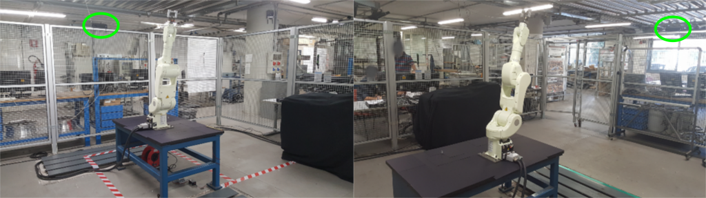
The safety system is based on two Microsoft Kinect v2 Time-Of-Flight (TOF) cameras. Each TOF camera measures the 3D position of each point in the scene evaluating the time-of-flight of a light signal emitted by the camera and reflected by each point. The cameras are placed on the safety cage of a robotic cell (Figure 1) so that the respective field of view covers the entire robotic working space. The 3D point clouds acquired by the TOF cameras are aligned with respect to a common reference system using a suitable calibration procedure [1].
Figure 1 - Positions of the TOF cameras on the robotic cell.
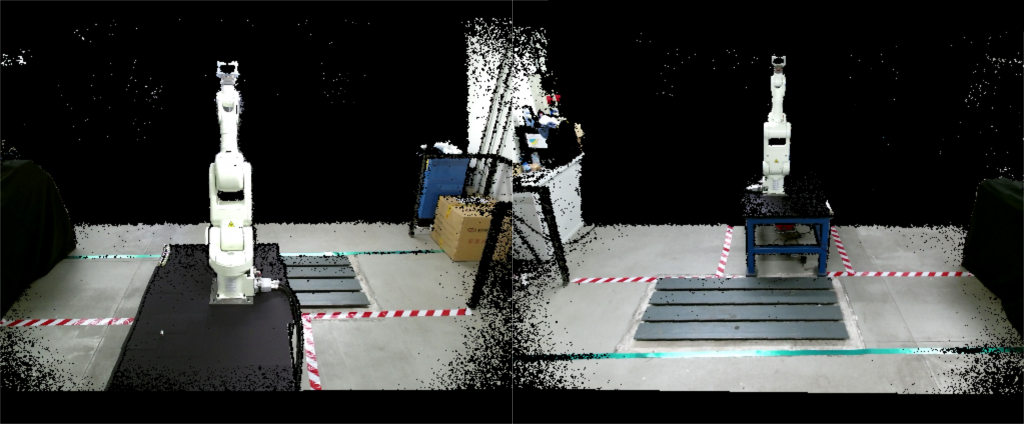
The robot and human detections are developed analyzing the RGB-D images (Figure 2) acquired by the cameras. These images contain both the RGB information and the depth information of each point in the scene.
Figure 2 - RGB-D images captured by the two TOF cameras.
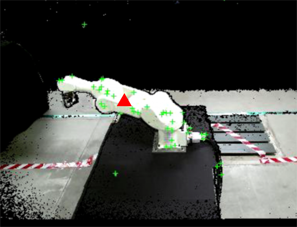
The robot recognition and tracking (Figure 3) is based on a KLT (Kanade-Lucas-Tomasi) algorithm, using the RGB data to detect the moving elements in a sequence of images [2]. The algorithm analyzes the RGB-D images and finds feature points such as edges and corners (see the green crosses in figure 3). The 3D position of the robot (represented by the red triangle in figure 3) is finally computed by averaging the 3D positions of feature points.
Figure 3 - Robot recognition and tracking.
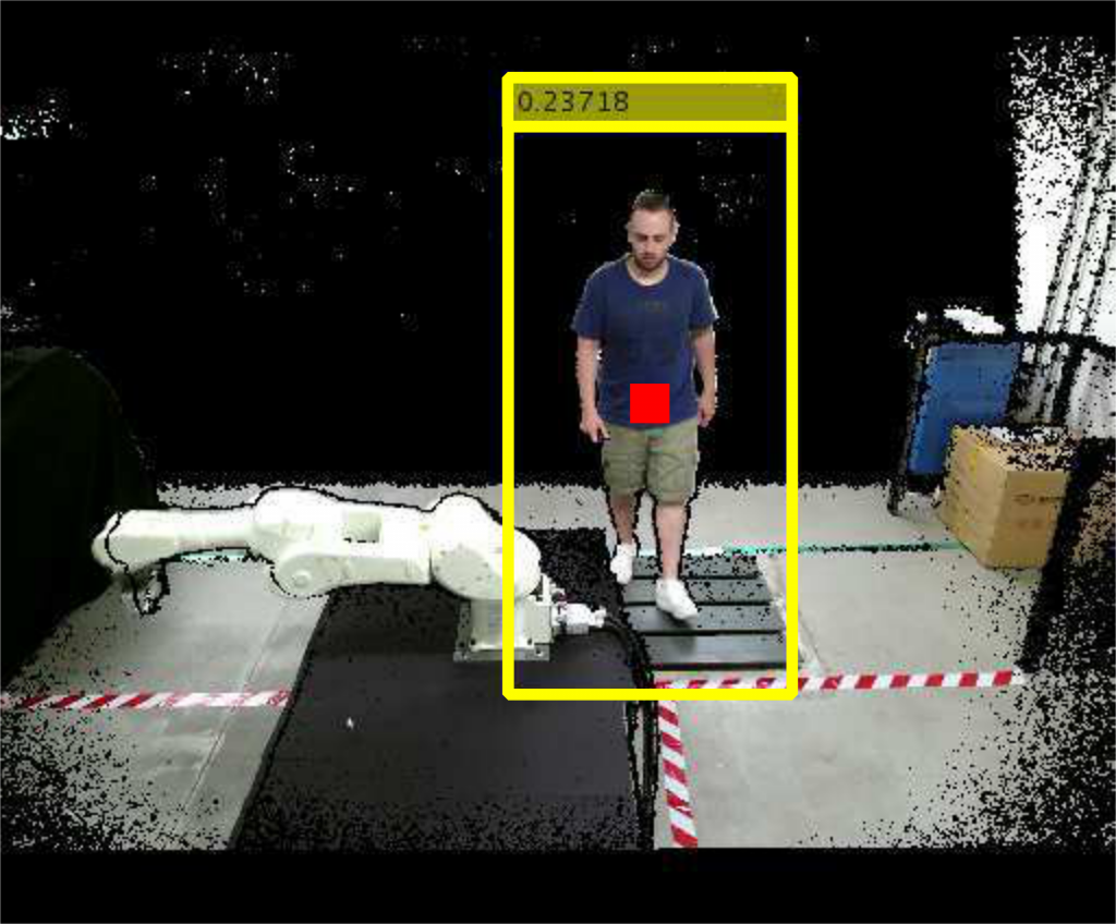
The human recognition and tracking (figure 4) is based on the HOG (Histogram of Oriented Gradient) algorithm [3]. The algorithm computes the 3D human position analyzing the gradient orientations of portions of RGB-D images and using them in a trained support vector machine (SVM). The human operator is framed in a yellow box after being detected, and his 3D center of mass is computed (see the red square in figure 4).
Figure 4 - Human recognition and tracking.
Three different safety strategies have been developed. The first strategy is based on the definition of suitable comfort zones of both the human operator and the robotic device. The second strategy implements virtual barriers separating the robot from the operator. The third strategy is based on the combined use of the comfort zones and of the virtual barriers.
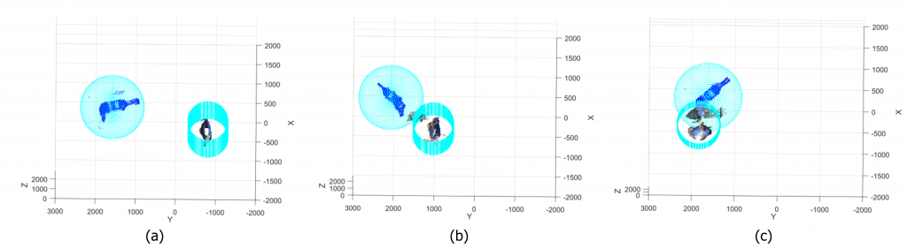
In the first strategy, a sphere and a cylinder are defined around the robot and the human respectively, and the distance between them is computed. Three different situations may occur (figure 5):
Safe situation (figure 5.a): the distance is higher than zero and the sphere and the cylinder are far from each other;
Warning situation (figure 5.b): the distance decreases toward zero and sphere and cylinder are very close;
Unsafe situation (figure 5.c): the distance is negative and sphere and cylinder collide.
Figure 5 - Monitored situations in the comfort zones strategy. Safe situation (a), warning situation (b), and unsafe situation (c).
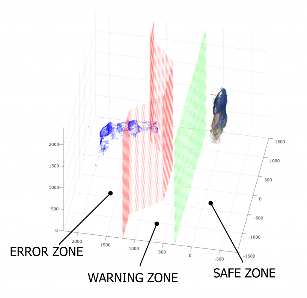
In the second strategy, two virtual barriers are defined (Figure 6). The former (displayed in green in figure 6) defines the limit between the safe zone (i.e. the zone where the human can move safely and the robot can not hit him) and the warning zone (i.e. the zone where the contact between human and robot can happen). The second barrier (displayed in red in figure 6) defines the limit between the warning zone and the error zone (i.e. the zone where the robot works and can easily hit the operator).
Figure 6 - Virtual barriers defined in the second strategy.
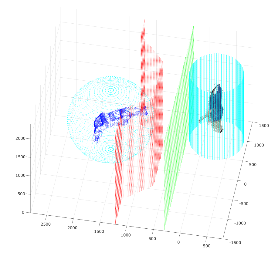
The third strategy is a combination of comfort zones and virtual barriers (figure 7). This strategy gives redundant information: both the human-robot distance and positions are considered.
Figure 7 - Redundant safety strategy: combination of comfort zones and virtual barriers.
Conclusions
The safety system shows good performances:
The robotic device is always recognized;
The human operator is recognized when he moves frontally with respect to the TOF cameras. The human recognition must be improved (for example increasing the number of TOF cameras) in case the human operator moves transversally with respect to the TOF cameras;
The safety situations are always identified correctly. The algorithm classifies the safety situations with an average delay of 0.86 ± 0.63s (k=1). This can be improved using a real time hardware.
The aim of this project is to create a remote control system for a robotic arm controlled by using the Kinect v2sensor, to track the movements of the user arm, without any additional point of measurement (marker-less modality).
The Kinect camera acquires a 3D point cloud of the body and a skeleton representation of the gesture/pose is obtained using the SDK library software provided by the Kinect. The skeleton joints are tracked and used to estimate the angles.
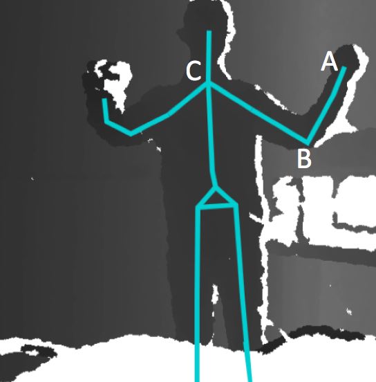
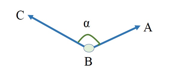
Figure 1 - The point cloud acquired by the Kinect, and the skeleton. Points A, B, and C are the joints.
Point A is the joint of the wrist, point B is the joint of the elbow and point C is the joint of the shoulder. In the three dimensional space, vectors BA and BC are calculated with using the space coordinates of points A, B and C, which are taken from the skeleton. Angle α is calculated by using the dot product of the two vectors.
The software has been developed in C# inVisual Studio 2015.
This project focuses on the e-manufacturing of complex parts by integrating smart additive manufacturing technologies to more traditional manufacturing processes, in view of obtaining sustainable, flexible, completely automatic and fast manufacturing (SMART MANUFACTURING).
The project is funded by the POR FESR 2014-2020: Linea R&S per Aggregazioni 2015 Regione Lombardia, and involves SMEs and Research Laboratories in strong cooperation to demonstrate the feasibility of producing industrial manufacts in the automotive industry.
The role of the laboratory is the study and the implementation of vision tools for the on-line control of the manufacturing process based on the additive approach.
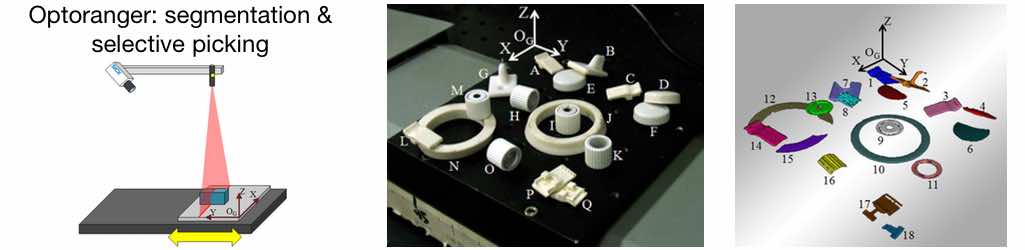
Optoranger is a new method, based on 3D vision, for the recognition of free-form objects in the presence of clutters and occlusions, ideal for robotic bin picking tasks. The method can be considered as a compromise between complexity and effectiveness.
A 3D point cloud representing the scene is generated by a triangulation-based scanning system, where a fast camera acquires a blade projected by a laser source. Image segmentation is based on 2D images, and on the estimation of the distances between point pairs, to search for empty areas. Object recognition is performed using commercial software libraries integrated with custom-developed segmentation algorithms, and a database of model clouds created by means of the same scanning system.
Experiments carried out to verify the performance of the method have been designed by randomly placing objects of different types in the Robot work area. The results demonstrate the excellent ability of the system to perform the bin picking procedure, and the reliability of the method proposed for automatic recognition of identity, position and orientation of the objects.
Recently, the integration of vision with robots has gained considerable attention from industry. Pick and place, sorting, assembling, cutting and welding processes are examples of applications which can have great advantage from the combination of information from 3D images with robot motion.
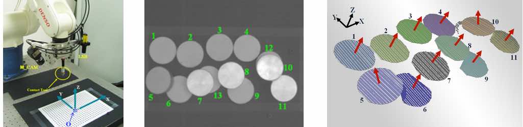
Our laboratory developed, in collaboration with DENSO EUROPE B. V., a system integrating 3D vision into robotic cells. The project led to the Roboscan system.
Roboscan is a Robot cell that combines 2D and 3D vision in a simple device, to aid a Robot manipulator in pick-and-place operations in a fast and accurate way. The optical head of Roboscan combines the two vision systems: the camera is used “stand-alone” in the 2D system, and combined to a laser slit projector in the 3D system, which operates in the triangulation mode. The 2D system, using suitable libraries, provides the preliminary 2D information to the 3D system to perform in a very fast, flexible and robust way the point cloud segmentation and fitting. The most innovative part of the system is represented by the use of robust 2D geometric template matching as a means to classify 3D objects. In this way, we avoid time-consuming 3D point cloud segmentation and 3D object classification, using 3D data only for estimating pose and orientation of the robot gripper. In addition, a novel approach to the template definition in the 2D geometric template matching is proposed, where the influence of surface reflectance and colour of the objects over the definition of the template geometry is minimized.