3D Acquisition and modeling for crime scene documentation

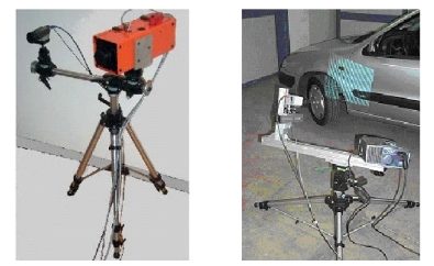
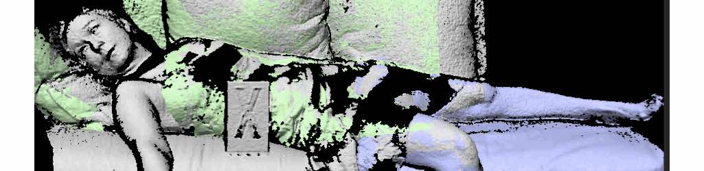
This project is aimed at testing the performance of 3D optical acquisition and reverse engineering to carry out the contact-less gauging of crime scenes for their documentation and analysis. In particular, the study focuses on two aspects. The former is the “in-field” measurement and modeling of crime scenes.

The activity carried out by the Laboratory staff deals with a number of significant cases. A comprehensive summary of the experiences is in the references below.

Related Publications

Cavagnini, G.; Scalvenzi, M.; Trebeschi, M.; Sansoni, G. “Reverse engineering from 3D optical acquisition: application to Crime Scene Investigation“, Proceedings of Virtual Modelling and Rapid Manufacturing, Advanced Research in Virtual and Rapid Prototyping, pp. 195-201. 2007

Sansoni, G.; Docchio, F.; Trebeschi, M.; Scalvenzi, M.; Cavagnini, G.; Cattaneo, C. “Application of three-dimensional optical acquisition to the documentation and the analysis of crime scenes and legal medicine inspection“, 2007 2nd International Workshop on Advances in Sensors and Interface, pp. 1-10. 2007

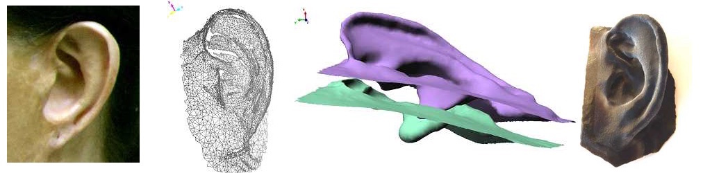
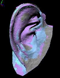
Sansoni, G.; Cattaneo, C.; Trebeschi, M.; Gibelli, D.; Porta, D.; Picozzi, M. “Feasibility of contactless 3D optical measurement for the analysis of bone and soft tissue lesions: new technologies and perspectives in forensic sciences“, Journal of Forensic Sciences, Vol. 54, no. 3, pp. 540-545. 2009

Sansoni, G.; Cattaneo, C.; Trebeschi, M.; Gibelli, D.; Poppa, P.; Porta, D.; Maldarella, M.; Picozzi, M. “Scene-of-Crime Analysis by a 3-Dimensional Optical Digitizer: A Useful Perspective for Forensic Science“, The American Journal of Forensic Medicine and Pathology, Vol. 32 no. 3, pp. 280-286. 2011

3D prosthetic applications to maxillo-facial defects

In the last years, prosthetic techniques have gained increased interest in post oncological reconstruction and in congenital defect treatment. Both the fuctional and the aesthetic characteristics of the prosthesis are crucial, in view of allowing the patient to overcome the social, psychological and economic problems deriving from their handicap.

Traditional reconstruction techniques present a number of lacks: the patient’s discomfort and stress, the inaccuracy of the replicas, and the dependence on the artistic skills of an experienced prosthetist. In addition, the mould production process is cumbersome, and time consuming. Finally, the overall process is not adaptive, i.e., whenever the existing prothesis should be replaced, the overall process must be carried out from scratch.

The purpose of this research activity is to develop a novel approach that combines optical three-dimensional acquisition, reverse engineering (RE) and rapid prototyping (RP) for the prosthetic reconstruction of facial prostheses.

Relevant Publications

Sansoni, G.; Cavagnini, G.; Docchio, F.; Gastaldi, G. “Virtual and physical prototyping by means of a 3D optical digitizer: application to facial prosthetic reconstruction“, Virtual and Physical Prototyping, Vol. 4, pp. 217-226. 2009

Sansoni, G.; Trebeschi, M.; Cavagnini, G.; Gastaldi, G. “3D Imaging acquisition, modeling and prototyping for facial defects reconstruction“, Proceedings of SPIE Three-Dimensional Imaging Metrology, Vol. 7239, pp. 1-8. 2009

Cavagnini, G.; Sansoni, G.; Vertuan, A.; Docchio, F. “3D optical Scanning: application to forensic medicine and to maxillofacial reconstruction“, Proceedings of International Conference on 3D Body Scanning Technologies, pp. 167-178. 2010

Study case: ear reconstruction

The example that we present in this article concerns the reconstruction of an ear. The approach is based on optical acquisition and modeling of the shapes. The final prosthesis is directly obtained from the model by means of rapid prototyping.

The patient’s defect is shown in the Fig. 1. The left ear is seriously damaged in consequence of a burn. To fabricate the prosthetic element, the right ear, shown in Fig. 2, was used as the template.

The test was performed as follows: first, we acquired the right, safe ear. We configured the digital scanner (Vivid 910 , Konica Minolta Inc.) in the MIDDLE configuration. Four views were acquired and aligned together. Then the triangle mesh was obtained and mirrored, in view of using it to model the prosthesis. The corresponding models are shown in Fig 3a, 3b and 3c. As a second step, the defect was gauged. The system configuration was the same as the one in the previous acquisition. Two views were sufficient to cover the whole surface. The mesh was created over the aligned views. The result is presented in Fig 3d.

The third step was the acquisition of the whole patient face in three views, as shown in Fig. 4. This model was used as the skeleton to align the mesh in Fig. 3d to the one in Fig. 3c. The model of the defect was aligned to the skeleton. Then the model of the ear was interactively aligned until the aesthetical appearance on the whole face was judged optimal. At this point, the skeleton was discarded. The two models were edited to fill residual holes and to reconstruct missing surface parts (mainly due to undercuts). Finally, they were finely connected in correspondence with their borders. The result of this step is shown in Fig. 5.

The mesh has been topologically controlled to produce the physical copy. This has been fabricated by means of rapid prototyping technology. The Connex 500 3D Printing System (Objet-Geometries Inc.) has been used. This machine is capable of printing parts and assemblies made of multiple model materials all in a single build. The materials used to fabricate the ear prosthetic element are the TangoBlackPlus Shore A85 for the area corresponding to the auricle surface, and the TangoBlackPlus Shore A27 for the areas at the borders of the ear. The ear was obtained in about one hour; the process is very cheap (the cost is in the order of 70 Euros). Fig. 6 shows the front and the back side of the final prosthesis.

Fig. 7 shows the patient’s face after the application of the prosthetic element. It is worth noting that, in this figure, the prosthesis color is not optimized yet. In fact, we wanted to check its functionality before optimizing it under the aesthetical point of view.

Fig. 7 - Patient face with prosthesis on.

In this process, patient comfort was optimal, since the acquisition step was quick, contactless and safe. The prosthesis try-in was unnecessary. The prototyping step was very cheap, and the overall time required was about six hours, plus the machining of the prosthesis.

OPL-3D_1.jpg

OPL-3D: a portable system for point cloud acquisition

OPL-3D has been specifically designed for applications of reverse engineering and rapid prototyping, as well as for applications of measurement and quality control.

The system exploits active stereo vision (the absolute approach is implemented) using time-multiplexing based on the Gray-Code-Phase-Shifting method.

The projector-camera pair

OPL-3D can host a wide variety of projectors. In the left figure in Fig. 1 the device is the ABW LCD 320: it is a microprocessor-controlled and column-driven projector, specifically intended to be used in this class of systems. Alternatively, those devices currently available for video projection can be succesfully used, as that one shown on the right figure in Fig. 1 (Kodak DP 900, based on DLP technology).

The detector is a commercial CCD video camera. In the configurations shown in Fig. 1, the camera is an inexpensive colour Hitachi KP D50, with standard resolution (752 x 582 px). However, any type of camera (black/white or colour, with single or multiple CCDs for colour separation, and with different pixel densities) can be mounted on the system, depending on the application and on the projector used. In Fig. 2, for example, a 1300 x 1030 px digital video camera (Basler model) is mounted, to acquire at the required resolution large fields of views

The mount

The projector and the camera are mounted onto a rigid bar, that can be easily moved around the scene by means of a tripod, and that holds the adjustment units for proper orientation. The mount is fully reconfigurable: all parameters can be varied according to the distance from the target, the required measurement resolution and the FoV (Fig. 3).

Given the fact that through sophisticated calibration procedures the system is able to finely estimate the operating parameters, no accurate positioning equipment (micropositioners, microrotators) is required, the only requirement being stability of the mount during the measurement procedure.

Fig. 4 shows two examples of on-site measurements of complex shapes where the full flexibility of the system was mandatory to perform the acquisition.

Fig. 3 - Images of the tripods used and of the equipment of the prototype.
Fig. 4 - Two on-site acquisition campaigns carried out by the Laboratory: the Winged Victory point cloud acquisition (left) and the Ferrari point cloud acquisition (right).

The electronic hardware

OPL-3D is equipped with a PC, that has the purpose of (i) driving the projector with the appropriate pattern sequence, (ii) acquiring the image sequences from the target, and (iii) elaborating the images. In addition, it contains all the features to perform sophisticated procedures for setting up and reconfiguration.

The PC is in the current configuration a Pentium III 900 MHz, 1 GB Ram, equipped with a Matrox Meteor II Frame Grabber. The Projector is operated by the PC through the Serial Connector.

PERFORMANCE

OPL-3D exhibits low-measurement uncertainty (120 mm) over large measurement areas (450 x 340 mm), linearly scalable in the case of smaller areas. Special care has been devoted to flexibility of use, in-field measurement setting, reconfigurability and robustness against environmental light changes and surface colour and texture

Fig. 5 shows the acquisition of the blue car already seen in Fig. 2. Multiview alignment and registration is performed by either purposely designed software or by means of commercially available products, depending on the complexity of the process.

Fig. 5 - Point Cloud obtained with every acquisition aligned to form a complete and dense reconstruction.

Technology transfer

OPL 3-D has been put into the market by Open Technologies s.r.l., Italy, a start-up company of the University of Brescia, under the Trade Name of 3DShape, in a manifold of versions, including sophisticated software for multi-view combination, point cloud manipulation and transformation, up to surface generation.

zeiss.jpg

To learn more on the combined use of CMMs with optical probes

The 3D Vision system used during the experimentation was the prototype 3D-Optolab, and the CMM was the Zeiss Prismo Vast 7D, equipped with the software Holos, installed at the DIMEG Metrological Laboratory. Both are shown in Fig. 1.

The proposed methodology does not foresee the physical integration of the two sensors; instead, their combination at the level of the measurement information is carried out, in a module for the intelligent aggregation of the information coming from the sensors.

Fig. 1 - The Zeiss Prismo Vast 7D (left) and the 3D-Optolab prototype (right) used for the project.

Fig. 2 schematically presents the method. The starting point is the acquisition of a number of clouds of points using 3D-Optolab. These are then imported into the CAD environment PRO/ENGINEER. The initial “rough” CAD model of the surface is obtained by using the modules available in the CAD environment PRO/E. This model is used to “feed” the CMM in the contact, accurate digitization step. The a-prori knowledge of a “rough” description of the surface allows an efficient programming of the scanning and digitizing path, and reduces the number of touch points and of the iterations needed to achieve the complete digitization of the object. The methods was tested on a number of objects: the experimental results are presented and discussed in the related publications at the bottom of the page.

Fig. 2 - Scheme of the developed procedure.

This research activity has been further developed in the frame of the project “Development of a novel methodology for the reverse engineering of complex, free-form surfaces, combining three-dimensional vision systems and Coordinate Measuring Machines” funded by the Italian Ministry of Research, in the year 2000. Two further Laboratories participate to this project: the DIMEG Metrological Laboratory, University of Padova, and the 3D Vision Group located at the Dipartimento di Elettronica e Informatica of the Milan Polytechnic. The objectives of this work are well described by the scheme in Fig. 3.

Fig. 3 - Objectives of the research work in a work-flow fashion.

Optical RE

The first aim of the project, (“Optical RE” in the Fig. 3) is to optimize the RE process as far as the time of execution, by creating a 3D model for the description of the object under test by using the optical digitization. This objective has been performed in the following steps:
  1. development of a reliable and easy to use optical digitizer, able to generate 3D point clouds that describe various parts of the object, each from a specific viewpoint; the measurement system, should be easily movable in space, in order to be able to “observe” the target object from different perspectives, and to create a set of point clouds that completely describe the object itself;
  2. development of procedures for the registration of the point clouds;
  3. development of the procedures for the creation, starting from the registered views, of 3D models of the shapes;
  4. metrological validation of the models by means of the CMM.

Optical/Contact RE

The second purpose of the project (“Optical/Contact RE” in Fig. 3) is to optimize the RE process from the viewpoint of the accuracy of the representation of the object, without increasing the process time. The approach is close to that one represented in Fig. 2; however, the initial representation of the CAD model has to be obtained starting from the above mentioned 3D models.

Metrological validation of Point Clouds

The third purpose of the project (“Metrological validation of point clouds” in the Fig. 3) is closely related to the activity aimed at metrologically validating, by means of the CMM, the point clouds generated by the optical digitizer.

Validation for RP

The final goal of the project (“Validation for RP” in Fig. 3) is the verification of the suitability of the 3D models for the Rapid Prototyping process.

Results obtained

The activity carried out by our Laboratory resulted in two research products. The former is the optical digitizer OPL-3D. The design and the development of the instrument have been completely performed by the Laboratory. The metrological characterization has been performed in collaboration with the Laboratory located in Padova.
The latter is a suite of software tools for the alignement of the point clouds in the multi-view acquisition process. These tools perform, in a semi-automatic way, the estimate of the rototranslation matrixes between pairs of point clouds. A further improvement is performed by the research Laboratory located in Milan, basically aimed at achieving a completely automatic process. Below you can find more details about the procedures.

Relevant Publications

Carbone, V.; Carocci, M.; Savio, E.; Sansoni, G.; De Chiffre, L. “Combination of a Vision System and a Coordinate Measuring Machine for the Reverse Engineering of Freeform Surfaces“, The International Journal of Advanced Manufacturing Technology, Vol. 17, no. 4, pp. 263–271. 2001

Sansoni, G.; Patrioli, A. “Combination of optical and mechanical digitizers for use of reverse engineering of CAD models“, Proceedings of Optoelectronic Distance Measurements and Applications (ODIMAPIII), pp. 301-306. 2001

Sansoni, G.; Carocci, M. “Integration of a 3D vision sensor and a CMM for reverse engineering applications“, Italy-Canada Workshop on 3D Digital Imaging and Modeling Applications of Heritage, Industry, Medicine & Land. 2001

Sansoni, G.; Carmignato, S.; Savio, E. “Validation of the measurement performance of a three-dimensional vision sensor by means of a coordinate measuring machine“, Proceedings of the 21st IEEE Instrumentation and Measurement Technology Conference, Vol. 1, pp. 773-778. 2004

To learn more on the Winged Victory of Brescia

The following sub-sections give an idea of the steps performed to carry out the project, and briefly present the results.

STEP 1: THE ACQUISITION OF THE POINT CLOUDS

Fig. 1 shows the point clouds acquired in correspondence with the head of the statue. Following the requirement of the archaeologist staff, the digitizer has been configured to acquire at the highest resolution, even at the expense of a considerable number of views and of an increased complexity of the alignment process. In the figure, 41 views are shown after the alignment (performed in means of the PolyWorks IM_Align module). Each one is characterized by a lateral resolution of 0.2 mm, and a height resolution from 0.1 mm to 0.3 mm, depending on the quality of the measurement. The measurement error spans from 0.050 mm to 0.2 mm: this variability mainly depends on the colour of the surface and on the presence of numerous undercuts, holes, and shadow regions.

The body of the statue has been acquired at lower resolutions, depending on the different body segments. Special care has been taken to avoid misalignment between the views, especially considering that the registration process was very complex, due to the high number of point clouds (more than 500) needed to fully digitize the statue. The measurement was performed in two steps: in the former, the skeleton was acquired (few, large views at low resolution, along suitable paths around the statue), to minimize the alignment error. In the latter, a high number of small views was captured and aligned to the skeleton. At the end of the process, the skeleton was eliminated.
Fig. 1 - Point cloud obtained of the head of the statue, very dense of details.

STEP 2: THE CREATION OF THE TRIANGLE MODELS

The IM_Merge module of Polyworks has been used to generate the polygon model from the measured data. Preliminarily, proper filteringdecimation and fusion of the partial views were carried out. Models characterized by different levels of adherence to the original point cloud have been created. Fig. 2 shows that one at the highest accuracy that has been used by the archaeologists to perform the measurements between the pairs of fiduciary points.

The measurement is very easy: the operator only selects on the display the two triangles representative of the fiduciary points and the software automatically evaluates and displays the corresponding distance. The measurement is very precise, due to (i) the high quality of the original data, (ii) the availability of the colour information acquired with the range data, and (iii) the density of the triangles within each single marker, as highlighted in the zoom of the figure. 
vittoria_wire.jpg
Fig. 2 - High accuracy section of the head with a zoom of the eye. The measurment is very precise!

STEP 3: THE EDITING OF THE TRIANGLE MODELS

The Polyworks IM_Edit module was very useful for the editing of the triangle models. The objective was to eliminate holes, and in general all the topological irregularities deriving from the invalid measured data. As an example, Fig. 3 shows the appearance of the high-resolution triangle model of the head before the editing operation, while Fig. 4 shows the edited mesh obtained: it is easy to note how all the holes disappeared, resulting in a very appealing rendering of the surface. This model, when the colour information is added, as in Fig. 5, is suited also for applications different with respect to the original, metrological one. These are, for example, the virtual musealization of the statue, and the creation of a topologically closed STL model, that allows us the creation of the copy of the statue.
vittoria_modello_testa.jpg
Fig. 5 - The head of the Winged Victory with the colour information added on top of the mesh.

STEP 4: THE CREATION OF SCALED REPRODUCTIONS OF THE STATUE

This step has resulted in the achievement of a number of copies of the Winged Victory. In Fig. 6 the 1:8 scaled copy of the head of the statue is shown. The work has been accomplished in the framework of the collaboration between our Laboratory and the Laboratory of Fast Prototyping of the University of Udine. A rapid prototyping machine has been used to produce the model, by means of the stereo lithography technique. The CIBATOOL SL 5190 has been used as the material. The overall dimension of the prototype is 140 x 110 x 133 mm. The memory occupation of the original STL file was 10MB: it has been sent via internet to the Laboratory located in Udine. The time required to obtain the copy was 0.20 hours for the elaboration of the data, plus 15 hours for the prototypization.

Fig. 6 - The prototyped models of the Winged Victory head, before and after the colour application on top.

A suite of copies of the whole statue has been obtained in the framework of the collaboration between the Direzione Civici Musei di Arte e Storia of Brescia and the EOS Electro Optical Systems GmbH, located in Munich, Germany. The work led to the development of two 1:1 scaled copies of the statue have been produced. For them, the Laboratory has provided the high resolution STL file shown in Fig. 7 (16 millions of triangles).

The model was segmented into sub-parts, that were separately prototyped. Fig. 8 shows the copy of the statue that is currently placed in the hall of EOS gmbh, Robert-Stirling-Ring 1, 82152 Krailling Munchen DE.

Further experimentation dealing with the generation of the mathematics of the surfaces has been carried out. Obviously, we did not want to “redesign” the shape of the statue: instead, the objective was to verify the feasibility of the generation of the CAD model of the surfaces, in view of its use mainly in two applications. The former is the reconstruction of lost parts (for example, the fingers of the hands), the latter is the virtual modification of the relative position of sub-parts of the body. For example, this is the case of the position of the head of the statue, which seems excessively inclined with respect to the bust.

Step 5: the creation of the CAD models

The feasibility study has been performed on the head. The Raindrop Geomagic Studio 3.1 has been used. The triangle models of these two body segments have been imported as STL files from the PolyWorks suite. The Geomagic environment elaborated them and generated the CAD model in three steps. The first one allowed the determination of the patch layout (in a fully automatic way); the second one automatically identified a proper number of control points within each patch, the third one fitted the NURBS surfaces to the control points. The following figures show the process in the case of the head of the statue. It is worth noting the regularity of the surfaces at the borders of each patch (Fig. 9), the complexity of the CAD model (Fig. 10) and the adherence of the mathematics to the triangle model (Fig. 11).

Fig. 11 - The adherence of the rendered model on the point cloud measured one is really good, as highlighted in the figure.