
The following sub-sections give an idea of the steps performed to carry out the project, and briefly present the results.
STEP 1: THE ACQUISITION OF THE POINT CLOUDS
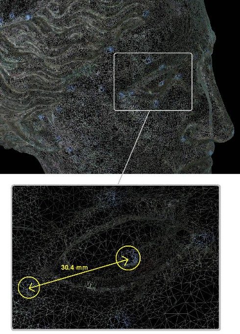
Fig. 1 shows the point clouds acquired in correspondence with the head of the statue. Following the requirement of the archaeologist staff, the digitizer has been configured to acquire at the highest resolution, even at the expense of a considerable number of views and of an increased complexity of the alignment process. In the figure, 41 views are shown after the alignment (performed in means of the PolyWorks IM_Align module). Each one is characterized by a lateral resolution of 0.2 mm, and a height resolution from 0.1 mm to 0.3 mm, depending on the quality of the measurement. The measurement error spans from 0.050 mm to 0.2 mm: this variability mainly depends on the colour of the surface and on the presence of numerous undercuts, holes, and shadow regions.

STEP 2: THE CREATION OF THE TRIANGLE MODELS
The measurement is very easy: the operator only selects on the display the two triangles representative of the fiduciary points and the software automatically evaluates and displays the corresponding distance. The measurement is very precise, due to (i) the high quality of the original data, (ii) the availability of the colour information acquired with the range data, and (iii) the density of the triangles within each single marker, as highlighted in the zoom of the figure.
STEP 3: THE EDITING OF THE TRIANGLE MODELS
STEP 4: THE CREATION OF SCALED REPRODUCTIONS OF THE STATUE
This step has resulted in the achievement of a number of copies of the Winged Victory. In Fig. 6 the 1:8 scaled copy of the head of the statue is shown. The work has been accomplished in the framework of the collaboration between our Laboratory and the Laboratory of Fast Prototyping of the University of Udine. A rapid prototyping machine has been used to produce the model, by means of the stereo lithography technique. The CIBATOOL SL 5190 has been used as the material. The overall dimension of the prototype is 140 x 110 x 133 mm. The memory occupation of the original STL file was 10MB: it has been sent via internet to the Laboratory located in Udine. The time required to obtain the copy was 0.20 hours for the elaboration of the data, plus 15 hours for the prototypization.

A suite of copies of the whole statue has been obtained in the framework of the collaboration between the Direzione Civici Musei di Arte e Storia of Brescia and the EOS Electro Optical Systems GmbH, located in Munich, Germany. The work led to the development of two 1:1 scaled copies of the statue have been produced. For them, the Laboratory has provided the high resolution STL file shown in Fig. 7 (16 millions of triangles).
The model was segmented into sub-parts, that were separately prototyped. Fig. 8 shows the copy of the statue that is currently placed in the hall of EOS gmbh, Robert-Stirling-Ring 1, 82152 Krailling Munchen DE.
Further experimentation dealing with the generation of the mathematics of the surfaces has been carried out. Obviously, we did not want to “redesign” the shape of the statue: instead, the objective was to verify the feasibility of the generation of the CAD model of the surfaces, in view of its use mainly in two applications. The former is the reconstruction of lost parts (for example, the fingers of the hands), the latter is the virtual modification of the relative position of sub-parts of the body. For example, this is the case of the position of the head of the statue, which seems excessively inclined with respect to the bust.
Step 5: the creation of the CAD models
The feasibility study has been performed on the head. The Raindrop Geomagic Studio 3.1 has been used. The triangle models of these two body segments have been imported as STL files from the PolyWorks suite. The Geomagic environment elaborated them and generated the CAD model in three steps. The first one allowed the determination of the patch layout (in a fully automatic way); the second one automatically identified a proper number of control points within each patch, the third one fitted the NURBS surfaces to the control points. The following figures show the process in the case of the head of the statue. It is worth noting the regularity of the surfaces at the borders of each patch (Fig. 9), the complexity of the CAD model (Fig. 10) and the adherence of the mathematics to the triangle model (Fig. 11).
