Commercial software for Reverse Engineering

The softwares

Two commercial software suites are successfully used by the Group to carry out the reverse engineering of very complex objects. These are the Polyworks 7.0 suite and the Raindrop Geomagic Studio 3.1 suite of programs.

Polyworks is specifically designed to obtain triangle meshes from point clouds. The IM-Align module is very powerful and allows us to perform the multiview acquisition when the number of point clouds is very high (from 30 to 500). The IM-Merge, IM-Edit and IM-Compress are used to create the triangle models, depending on the level of accuracy of the original point cloud, and on the accuracy required to the polygonal mesh. The work environment allows the operator to finely adjust, smooth, fill, join, close the final model by means of a considerable number of functions.

The Geomagic environment is designed to produce, from the original point cloud, the triangle models and the NURBS models. These are obtained starting from the triangle meshes. The software privileges the automation of the whole process with respect to the fine, local adjusting of the surfaces.

In the work carried out untill now, the Polyworks Suite has been preferred when (i) the measurement targets are characterised by a high level of complexity and by the presence of small details, (ii) the acquired point clouds result into a high number of invalid points and the quality of the measurement is not optimal, and (iii) the reverse engineering process requires only the generation of triangles. This is the case of the experimental work carried out in the summer of 2001 at the Civici Musei of Brescia, dealing with the modelling of the ‘Winged Victory’.

On the other hand, the Geomagic suite is used when (i) the shapes are generally regular and are efficiently elaborated (edited, filtered, topologically controlled) in an automatic way, (ii) the process time has to be kept low, (iii) the CAD model is required. The reverse engineering of the Ferrari 250MM has been performed in spring 2002 by using this software environment.

A Reverse Engineering example

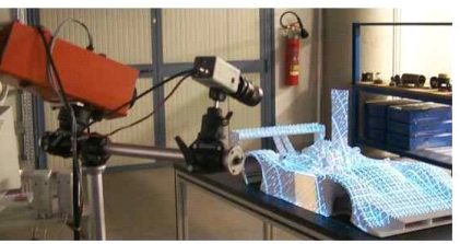
The example reported here fully documents the reverse engineering process of the object in Fig. 1 carried out by using both the mentioned software products.
It is a 1:4 scaled model of a F333 (by courtesy of Ferrari and Officine Michelotto). The following figures illustrate all the main steps of the test. These are:

  1. the optical acquisition by means of OPL-3D (Fig. 1);
  2. the alignment process to obtain the point cloud of the whole object (Fig. 2). It has been performed by using the IM-Align module;
  3. the generation of the triangle model (Fig. 3). IM-Merge has been used in this step: it allowed the creation of a number of models at different levels of detail;
  4. the generation of the CAD model (Fig. 4). It has been obtained by exporting the triangle model from the Polyworks environment to the Geomagic Environment (the STL format has been used), and by exploiting the powerful tools for the generation of the patch layout and the matematics of the surfaces available in Geomagic Studio 3.0. 

Fig. 5 shows the rendered view of the CAD model.

Fig.1 - The acquisition of the F333 by means of OPL-3D.
zeiss.jpg

To learn more on the combined use of CMMs with optical probes

The 3D Vision system used during the experimentation was the prototype 3D-Optolab, and the CMM was the Zeiss Prismo Vast 7D, equipped with the software Holos, installed at the DIMEG Metrological Laboratory. Both are shown in Fig. 1.

The proposed methodology does not foresee the physical integration of the two sensors; instead, their combination at the level of the measurement information is carried out, in a module for the intelligent aggregation of the information coming from the sensors.

Fig. 1 - The Zeiss Prismo Vast 7D (left) and the 3D-Optolab prototype (right) used for the project.

Fig. 2 schematically presents the method. The starting point is the acquisition of a number of clouds of points using 3D-Optolab. These are then imported into the CAD environment PRO/ENGINEER. The initial “rough” CAD model of the surface is obtained by using the modules available in the CAD environment PRO/E. This model is used to “feed” the CMM in the contact, accurate digitization step. The a-prori knowledge of a “rough” description of the surface allows an efficient programming of the scanning and digitizing path, and reduces the number of touch points and of the iterations needed to achieve the complete digitization of the object. The methods was tested on a number of objects: the experimental results are presented and discussed in the related publications at the bottom of the page.

Fig. 2 - Scheme of the developed procedure.

This research activity has been further developed in the frame of the project “Development of a novel methodology for the reverse engineering of complex, free-form surfaces, combining three-dimensional vision systems and Coordinate Measuring Machines” funded by the Italian Ministry of Research, in the year 2000. Two further Laboratories participate to this project: the DIMEG Metrological Laboratory, University of Padova, and the 3D Vision Group located at the Dipartimento di Elettronica e Informatica of the Milan Polytechnic. The objectives of this work are well described by the scheme in Fig. 3.

Fig. 3 - Objectives of the research work in a work-flow fashion.

Optical RE

The first aim of the project, (“Optical RE” in the Fig. 3) is to optimize the RE process as far as the time of execution, by creating a 3D model for the description of the object under test by using the optical digitization. This objective has been performed in the following steps:
  1. development of a reliable and easy to use optical digitizer, able to generate 3D point clouds that describe various parts of the object, each from a specific viewpoint; the measurement system, should be easily movable in space, in order to be able to “observe” the target object from different perspectives, and to create a set of point clouds that completely describe the object itself;
  2. development of procedures for the registration of the point clouds;
  3. development of the procedures for the creation, starting from the registered views, of 3D models of the shapes;
  4. metrological validation of the models by means of the CMM.

Optical/Contact RE

The second purpose of the project (“Optical/Contact RE” in Fig. 3) is to optimize the RE process from the viewpoint of the accuracy of the representation of the object, without increasing the process time. The approach is close to that one represented in Fig. 2; however, the initial representation of the CAD model has to be obtained starting from the above mentioned 3D models.

Metrological validation of Point Clouds

The third purpose of the project (“Metrological validation of point clouds” in the Fig. 3) is closely related to the activity aimed at metrologically validating, by means of the CMM, the point clouds generated by the optical digitizer.

Validation for RP

The final goal of the project (“Validation for RP” in Fig. 3) is the verification of the suitability of the 3D models for the Rapid Prototyping process.

Results obtained

The activity carried out by our Laboratory resulted in two research products. The former is the optical digitizer OPL-3D. The design and the development of the instrument have been completely performed by the Laboratory. The metrological characterization has been performed in collaboration with the Laboratory located in Padova.
The latter is a suite of software tools for the alignement of the point clouds in the multi-view acquisition process. These tools perform, in a semi-automatic way, the estimate of the rototranslation matrixes between pairs of point clouds. A further improvement is performed by the research Laboratory located in Milan, basically aimed at achieving a completely automatic process. Below you can find more details about the procedures.

Relevant Publications

Carbone, V.; Carocci, M.; Savio, E.; Sansoni, G.; De Chiffre, L. “Combination of a Vision System and a Coordinate Measuring Machine for the Reverse Engineering of Freeform Surfaces“, The International Journal of Advanced Manufacturing Technology, Vol. 17, no. 4, pp. 263–271. 2001

Sansoni, G.; Patrioli, A. “Combination of optical and mechanical digitizers for use of reverse engineering of CAD models“, Proceedings of Optoelectronic Distance Measurements and Applications (ODIMAPIII), pp. 301-306. 2001

Sansoni, G.; Carocci, M. “Integration of a 3D vision sensor and a CMM for reverse engineering applications“, Italy-Canada Workshop on 3D Digital Imaging and Modeling Applications of Heritage, Industry, Medicine & Land. 2001

Sansoni, G.; Carmignato, S.; Savio, E. “Validation of the measurement performance of a three-dimensional vision sensor by means of a coordinate measuring machine“, Proceedings of the 21st IEEE Instrumentation and Measurement Technology Conference, Vol. 1, pp. 773-778. 2004