The softwares
Two commercial software suites are successfully used by the Group to carry out the reverse engineering of very complex objects. These are the Polyworks 7.0 suite and the Raindrop Geomagic Studio 3.1 suite of programs.
Polyworks is specifically designed to obtain triangle meshes from point clouds. The IM-Align module is very powerful and allows us to perform the multiview acquisition when the number of point clouds is very high (from 30 to 500). The IM-Merge, IM-Edit and IM-Compress are used to create the triangle models, depending on the level of accuracy of the original point cloud, and on the accuracy required to the polygonal mesh. The work environment allows the operator to finely adjust, smooth, fill, join, close the final model by means of a considerable number of functions.
The Geomagic environment is designed to produce, from the original point cloud, the triangle models and the NURBS models. These are obtained starting from the triangle meshes. The software privileges the automation of the whole process with respect to the fine, local adjusting of the surfaces.
In the work carried out untill now, the Polyworks Suite has been preferred when (i) the measurement targets are characterised by a high level of complexity and by the presence of small details, (ii) the acquired point clouds result into a high number of invalid points and the quality of the measurement is not optimal, and (iii) the reverse engineering process requires only the generation of triangles. This is the case of the experimental work carried out in the summer of 2001 at the Civici Musei of Brescia, dealing with the modelling of the ‘Winged Victory’.
On the other hand, the Geomagic suite is used when (i) the shapes are generally regular and are efficiently elaborated (edited, filtered, topologically controlled) in an automatic way, (ii) the process time has to be kept low, (iii) the CAD model is required. The reverse engineering of the Ferrari 250MM has been performed in spring 2002 by using this software environment.
A Reverse Engineering example
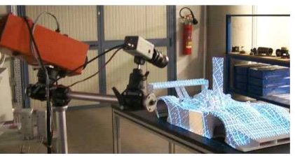
The example reported here fully documents the reverse engineering process of the object in Fig. 1 carried out by using both the mentioned software products.
It is a 1:4 scaled model of a F333 (by courtesy of Ferrari and Officine Michelotto). The following figures illustrate all the main steps of the test. These are:
- the optical acquisition by means of OPL-3D (Fig. 1);
- the alignment process to obtain the point cloud of the whole object (Fig. 2). It has been performed by using the IM-Align module;
- the generation of the triangle model (Fig. 3). IM-Merge has been used in this step: it allowed the creation of a number of models at different levels of detail;
- the generation of the CAD model (Fig. 4). It has been obtained by exporting the triangle model from the Polyworks environment to the Geomagic Environment (the STL format has been used), and by exploiting the powerful tools for the generation of the patch layout and the matematics of the surfaces available in Geomagic Studio 3.0.
Fig. 5 shows the rendered view of the CAD model.


