If you want to know more about our projects about measurement systems for exoskeleton users, here you can find a brief overview presented during the last COST action meeting on wearable exoskeletons.
The communication and collaboration between humans and robots is one of main principles of the fourth industrial revolution (Industry 4.0). In the next years, robots and humans will become co-workers, sharing the same working space and helping each other. A robot intended for collaboration with humans has to be equipped with safety components, which are different from the standard ones (cages, laser scans, etc.).
In this project, a safety system for applications of human-robot collaboration has been developed. The system is able to:
recognize and track the robot;
recognize and track the human operator;
measure the distance between them;
discriminate between safe and unsafe situations.
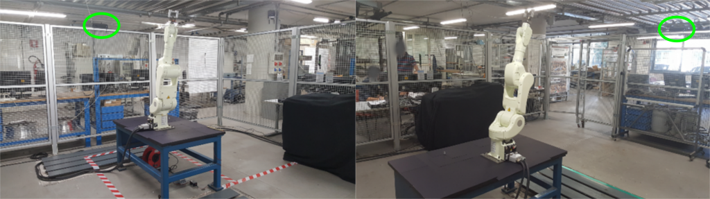
The safety system is based on two Microsoft Kinect v2 Time-Of-Flight (TOF) cameras. Each TOF camera measures the 3D position of each point in the scene evaluating the time-of-flight of a light signal emitted by the camera and reflected by each point. The cameras are placed on the safety cage of a robotic cell (Figure 1) so that the respective field of view covers the entire robotic working space. The 3D point clouds acquired by the TOF cameras are aligned with respect to a common reference system using a suitable calibration procedure [1].
Figure 1 - Positions of the TOF cameras on the robotic cell.
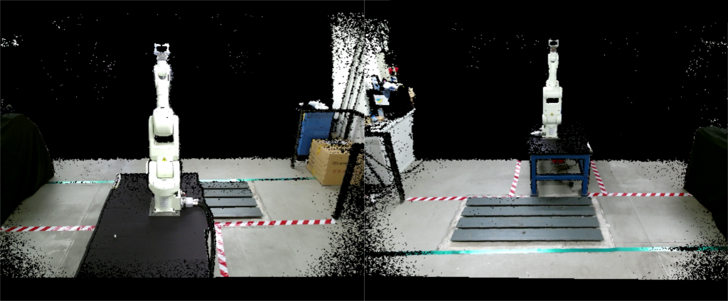
The robot and human detections are developed analyzing the RGB-D images (Figure 2) acquired by the cameras. These images contain both the RGB information and the depth information of each point in the scene.
Figure 2 - RGB-D images captured by the two TOF cameras.
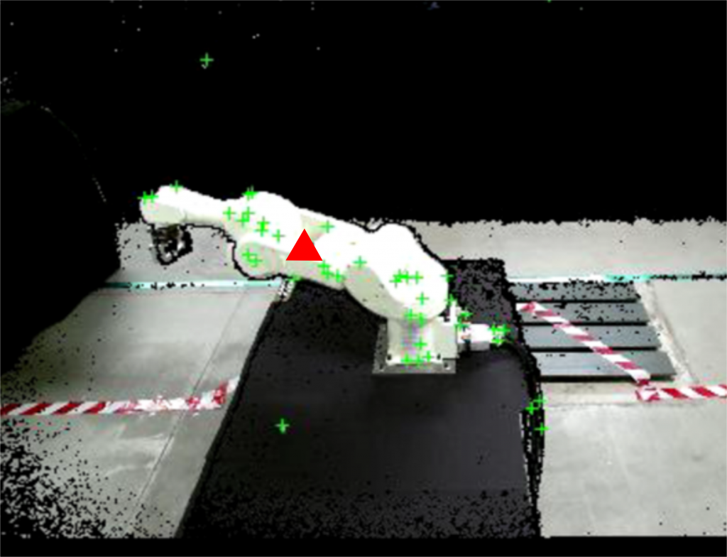
The robot recognition and tracking (Figure 3) is based on a KLT (Kanade-Lucas-Tomasi) algorithm, using the RGB data to detect the moving elements in a sequence of images [2]. The algorithm analyzes the RGB-D images and finds feature points such as edges and corners (see the green crosses in figure 3). The 3D position of the robot (represented by the red triangle in figure 3) is finally computed by averaging the 3D positions of feature points.
Figure 3 - Robot recognition and tracking.
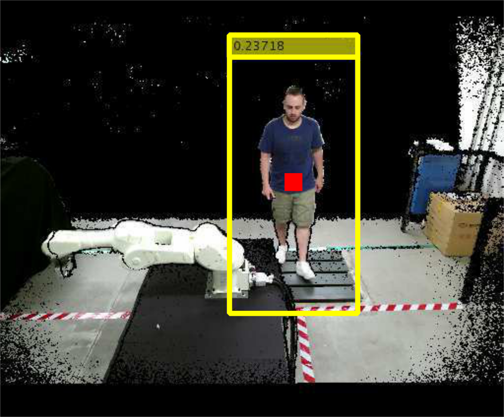
The human recognition and tracking (figure 4) is based on the HOG (Histogram of Oriented Gradient) algorithm [3]. The algorithm computes the 3D human position analyzing the gradient orientations of portions of RGB-D images and using them in a trained support vector machine (SVM). The human operator is framed in a yellow box after being detected, and his 3D center of mass is computed (see the red square in figure 4).
Figure 4 - Human recognition and tracking.
Three different safety strategies have been developed. The first strategy is based on the definition of suitable comfort zones of both the human operator and the robotic device. The second strategy implements virtual barriers separating the robot from the operator. The third strategy is based on the combined use of the comfort zones and of the virtual barriers.
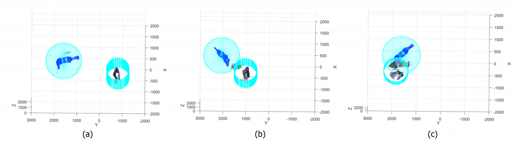
In the first strategy, a sphere and a cylinder are defined around the robot and the human respectively, and the distance between them is computed. Three different situations may occur (figure 5):
Safe situation (figure 5.a): the distance is higher than zero and the sphere and the cylinder are far from each other;
Warning situation (figure 5.b): the distance decreases toward zero and sphere and cylinder are very close;
Unsafe situation (figure 5.c): the distance is negative and sphere and cylinder collide.
Figure 5 - Monitored situations in the comfort zones strategy. Safe situation (a), warning situation (b), and unsafe situation (c).
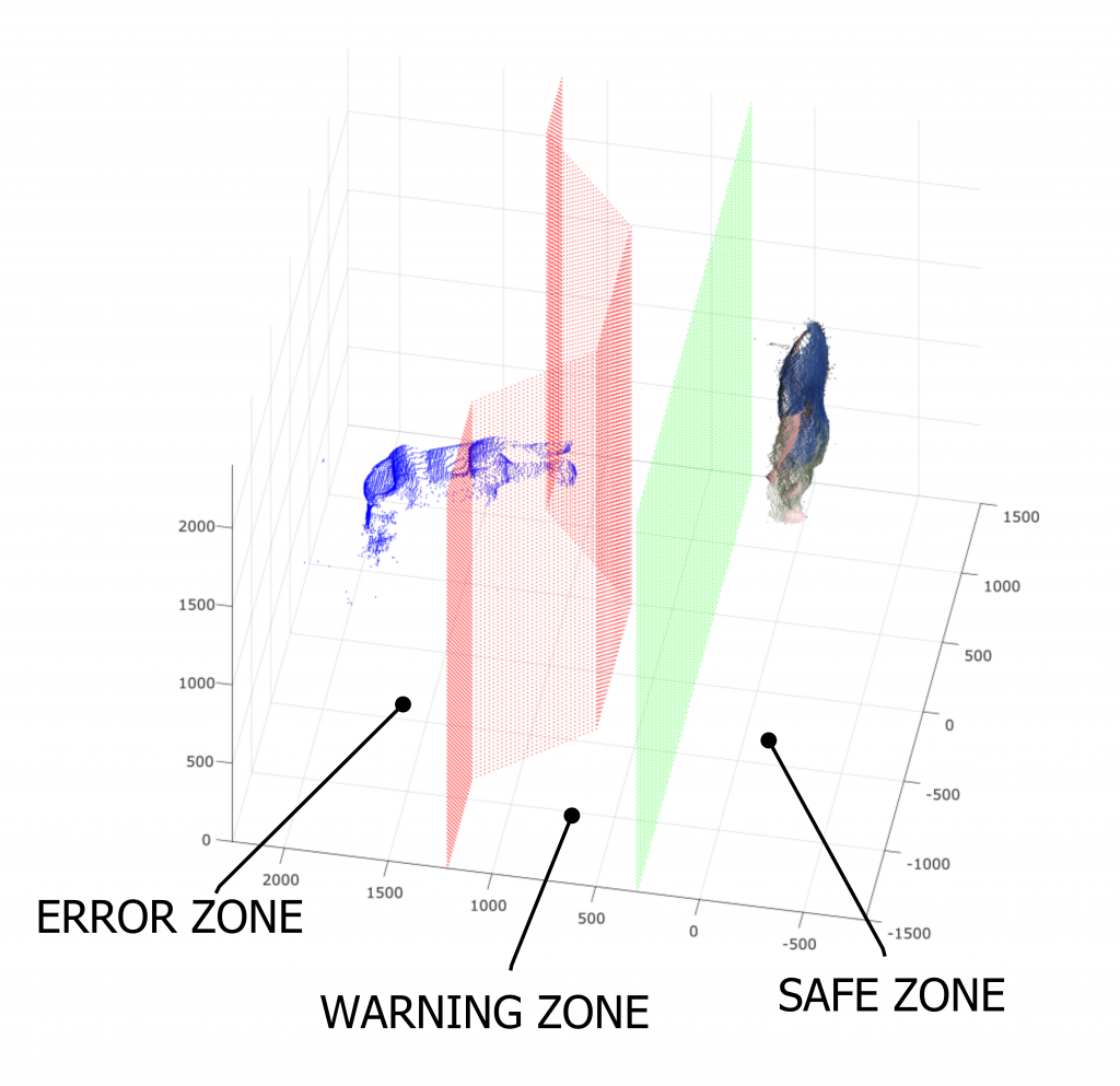
In the second strategy, two virtual barriers are defined (Figure 6). The former (displayed in green in figure 6) defines the limit between the safe zone (i.e. the zone where the human can move safely and the robot can not hit him) and the warning zone (i.e. the zone where the contact between human and robot can happen). The second barrier (displayed in red in figure 6) defines the limit between the warning zone and the error zone (i.e. the zone where the robot works and can easily hit the operator).
Figure 6 - Virtual barriers defined in the second strategy.
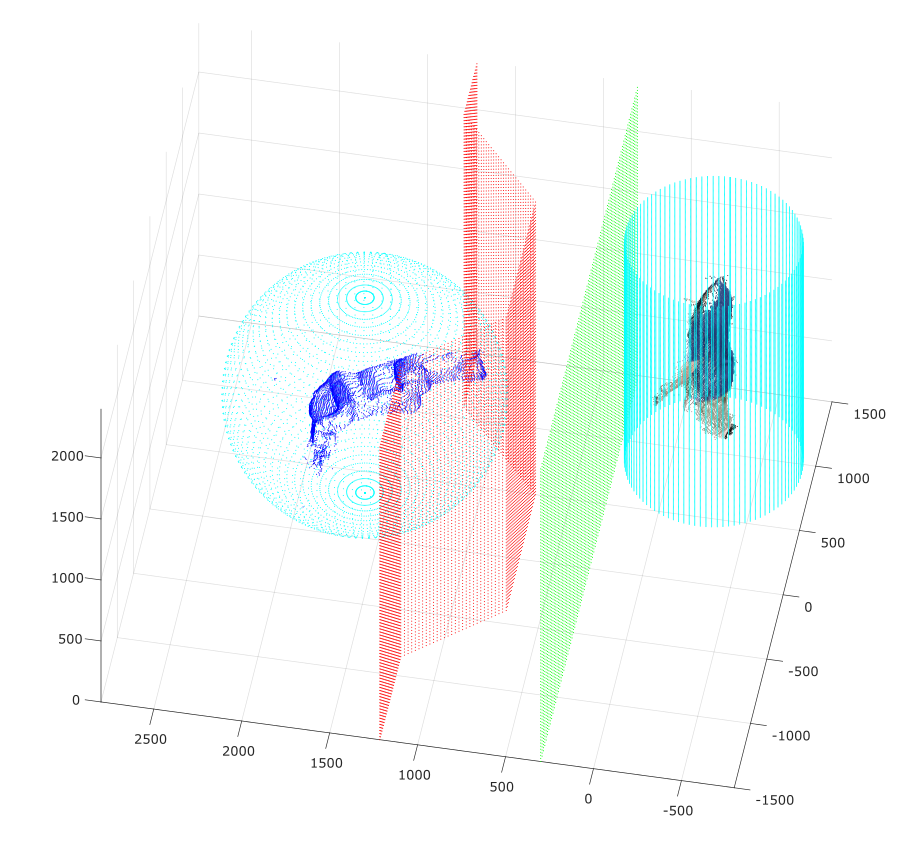
The third strategy is a combination of comfort zones and virtual barriers (figure 7). This strategy gives redundant information: both the human-robot distance and positions are considered.
Figure 7 - Redundant safety strategy: combination of comfort zones and virtual barriers.
Conclusions
The safety system shows good performances:
The robotic device is always recognized;
The human operator is recognized when he moves frontally with respect to the TOF cameras. The human recognition must be improved (for example increasing the number of TOF cameras) in case the human operator moves transversally with respect to the TOF cameras;
The safety situations are always identified correctly. The algorithm classifies the safety situations with an average delay of 0.86 ± 0.63s (k=1). This can be improved using a real time hardware.
The aim of this project is to create a remote control system for a robotic arm controlled by using the Kinect v2sensor, to track the movements of the user arm, without any additional point of measurement (marker-less modality).
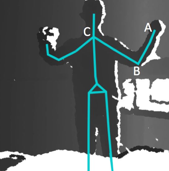
The Kinect camera acquires a 3D point cloud of the body and a skeleton representation of the gesture/pose is obtained using the SDK library software provided by the Kinect. The skeleton joints are tracked and used to estimate the angles.
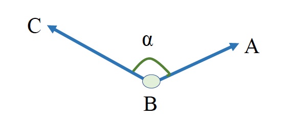
Figure 1 - The point cloud acquired by the Kinect, and the skeleton. Points A, B, and C are the joints.
Point A is the joint of the wrist, point B is the joint of the elbow and point C is the joint of the shoulder. In the three dimensional space, vectors BA and BC are calculated with using the space coordinates of points A, B and C, which are taken from the skeleton. Angle α is calculated by using the dot product of the two vectors.
The software has been developed in C# inVisual Studio 2015.
Subjects with complete spinal cord injury (SCI) experience several limitations in their daily activities. Rehabilitative gait training by means of powered gait orthosis (PGO) has been shown to decrease the risk of secondary pathologies (e.g. skin injuries, osteoporosis, cardiovascular issues) and can significantly improve the quality of life, provided that they are used on a regular basis and in the correct way. The traditional training is based on three steps: gait trial, data analysis, and gait correction. Gait is monitored using force platforms and dedicated instrumentation directly applied to the patient (EMGs, IMUs, markers). These devices require time to be positioned and care by the patient while walking. Data analysis and gait correction are totally dependent on the therapist experience. The process must be performed in specialized centers and is very time consuming. This leads to a high cost for the community health services.
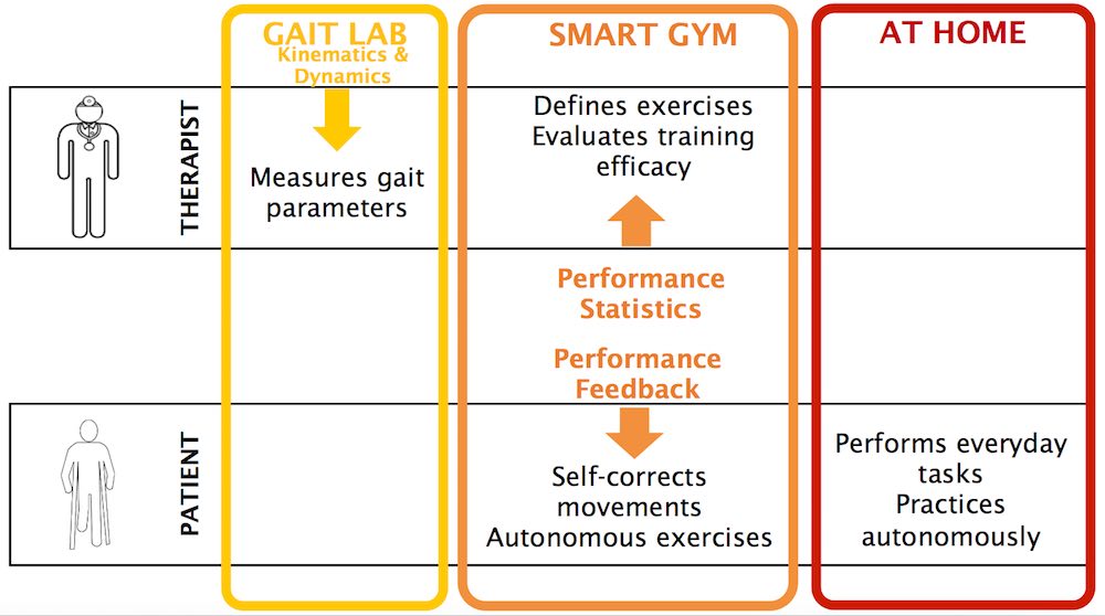
Costs and efforts needed for longer training sessions could be reduced by the availability of a SMART GYM environment to:
provide real-time feedback directly to the patient about his/her gait performance;
provide information to clinicians and therapists to remotely monitor the patient;
involve the patient in personalized gait exercises depending on his/her performance in time;
allow the patient to train on his/her own, along paths longer than those permitted by the limited room available in gait laboratories.
Figure 1 - The smart gym objectives.
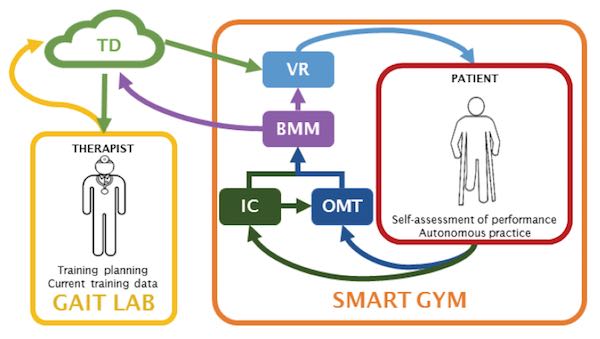
The SMART GYM components
BMM (BioMechanical Model):this component evaluates patient posture and motion in real time. The BMM is fed with (i) the spatiotemporal gait parameters, (ii) the kinematics of the lower limbs, and (iii) the kinematics of the upper limbs;
IC (Instrumented Crutches): this system is specifically designed measure the kinematics of the lower limbs and the spatiotemporal gait parameters;
OMT (Optical Motion Tracking): this system estimates the upper limb kinematics using a suitable set of Kinect devices;
VR (Virtual Reality): this system carries out the self-training of the patient;
TD (Therapist Dashboard): a dedicated software service that collects the data from BMM and allows the therapist to follow the patient progress remotely, an to plan new train patterns.
Figure 2 - The SMART GYM components.
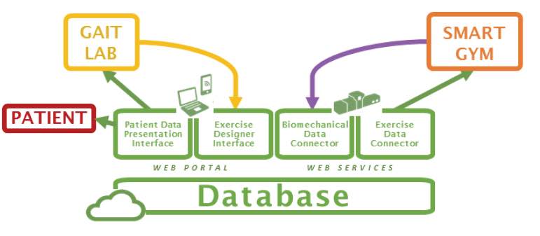
Figure 3 - The therapist dashboard architecture.
Novelty of the Project
The IC system, based on “A Vision System that walks with the patient” (challenging, but very promising);
The OMT based on multiple Kinect devices is new with respect to state of the art, since most applications are performed using a single device.
The combination of the OMT in the VR system will lead to the realization of a novel human machine interface, able to accurately render the posture of the whole body.
The paradigm of adaptiveness that lays under the BMMsystem is novel, as it requires new approaches to the estimate of the gait and posture indices.
The smart gym project is highly interdisciplinary: knowledge and expertise from the mechanical and the electronic measurement community will allow the development of either sensors (both contact and contact-less), models (both in the biomechanics and in the artificial vision contexts), measurement procedures, virtual reality scenarios and clinical experimentation, which will be fused together and integrated using ICT technologies. This aspect well fits one of the most significant Horizon 2020 priority, i.e., transversality.
Impact of the Project
The SMART GYM represents a new environment where the patient can practice autonomously and yet under the therapist control;
The SMART GYM will reduce community costs;
The SMART GYM will be valuable for elderly people;
The SMART GYM will be valuable even for healthy people.
This project focuses on the e-manufacturing of complex parts by integrating smart additive manufacturing technologies to more traditional manufacturing processes, in view of obtaining sustainable, flexible, completely automatic and fast manufacturing (SMART MANUFACTURING).
The project is funded by the POR FESR 2014-2020: Linea R&S per Aggregazioni 2015 Regione Lombardia, and involves SMEs and Research Laboratories in strong cooperation to demonstrate the feasibility of producing industrial manufacts in the automotive industry.
The role of the laboratory is the study and the implementation of vision tools for the on-line control of the manufacturing process based on the additive approach.
The accurate and timely monitoring of hypertension-related diseases is important for a population screening and follow up, to prevent the onset and to assure proper treatment. The evaluation of morphological characteristics of small resistance arteries in human beings in not easy. The gold standard is generally considered the evaluation of the media to lumen ratio of subcutaneous small vessels obtained by local biopsies and measured by wire or pressure micromyography.
However, non-invasive techniques for evaluation of retinal arterioles were proposed, in particular two approaches seem to provide interesting information: scanning laser Doppler flowmetry and adaptive optics; both of them provide an estimation of the wall to lumen ratio (WLR) of retinal arterioles.
The Laboratory is involved in the assessment of the efficiency and efficacy of a recently developed non invasive diagnostic instrument, able to provide high-quality images of the retina, by means of adaptive optics. In collaboration with the Chair of Internal Medicine of the University (Prof. D. Rizzoni), the instrument and its software are tested for accuracy and repeatability on artificial vessel models, and on a database of subjects.
Based on the data collected so far, the instrument performs in a quite satisfactory way as compared to the previously used techniques.
Rizzoni, D.; Agabiti Rosei, C.; De Ciuceis, C.; Semeraro, F.; Rizzoni, M.; Docchio, F. “New Methods to Study the Microcirculation“, American Journal of Hypertension, Vol 31, Issue 3, pp 265–273. 2018
Nardin, M.; Coschignano, M. A.; Rossini, C.; De Ciuceis, C.; Caletti, S.; Rizzoni, M.; Docchio, F.; Porteri, E.; Rizzoni, D. “Methods of evaluation of microvascular structure: state of the art“, European Journal of Translational and Clinical Medicine, Vol 1, pp 7-17. 2018
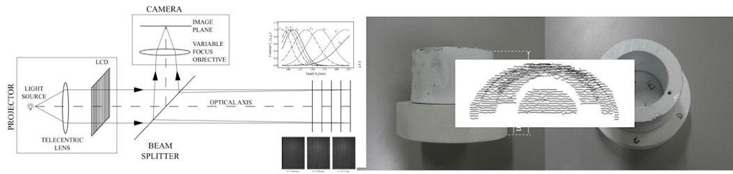
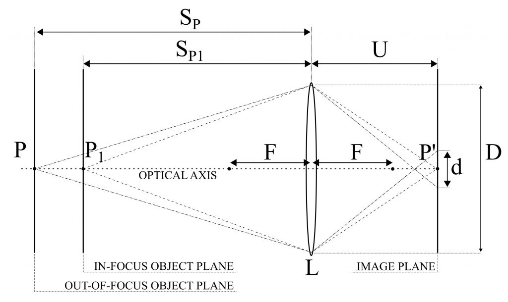
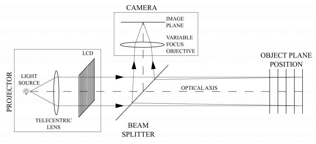
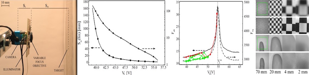
A novel Depth From Defocus (DFD) measurement system is has been developed. Here the extension of the measurement range is performed using an emergent technology based on liquid lenses. A suitable set of different focal lengths, obtained by properly changing the liquid lens supply voltage, provides multiple camera settings without duplicating the system elements or using moving parts.
A simple and compact setup, with a single camera/illuminator coaxial assembly is obtained. The measurement is based on an active DFD technique using modulation measurement profilometry(MMP) for the estimation of the contrast at each image point as a function of the depth range.
A suitable combination of multiple contrast curves, each one derived at a specific focal length, is proposed to extend the measurement range and to improve the measurement performances with respect to the state of the art.
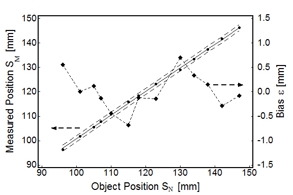
The system measurement errors are 0.53 mm over an extended measurement depth range of 135 mm, corresponding to 0.39 % of the depth range, resulting in an improved performance with respect to the state of the art DFD systems, for which typical values are in the 0.7-1.6 % of the depth range.
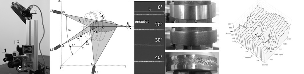
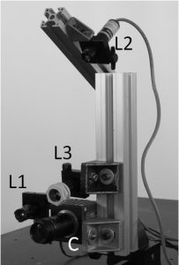
Rolling contact wear/fatigue tests on wheel/rail specimens are important to produce wheels and rails of new materials for improved lifetime and performance, able to work in harsh environments and at high rolling speeds. We have developed a novel non-invasive, all-optical system, based on a high-speed video camera and multiple laser illumination sources, which is able to continuously monitor the dynamics of the specimens used to test wheel and rail materials, in a Laboratory test bench.
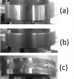
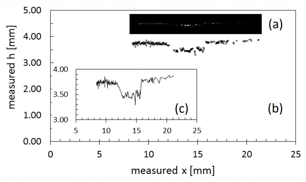
3D macro-topgraphy and angular position of the specimen are simultaneously performed, together with the acquisition of surface micro-topography, at speeds up to 500 rpm, making use of a fast camera and image processing algorithms. Synthetic indexes for surface micro-topography classification are defined, the 3D macro-topography is measured with a standard uncertainty down to 0.019 mm, and the angular position is measured on a purposely developed analog encoder with a standard uncertainty of 2.9°. The operate with very small camera exposure time enables to obtain blur-free images with excellent definition. The system will be described with the aid of end-cycle specimens, as well as of in-test specimens.
Vision-based measurement techniques have become very important in the biomedical field, especially for macro applications such as fingerprints detection, retinal measurements and melanomas analysis. These applications usually require fast and accurate focusing systems to rapidly acquire the optimal image for the successive elaborations. Applications in macro regions also need a stable focus to systems that suffer from low frequency vibrations due to the natural oscillations of the human body.
Liquid lens objectives have become popular in the last years thanks to their small dimensions (apertures goes from 3 mm to 10 mm), low power consumption (less than 0.1 mW) and fast response time (about 15 ms) [1]. These characteristics make the liquid lens objectives suitable for autofocusing systems, which require high velocity, good accuracy and good stability. The high-speed control of liquid lens objectives requires smart algorithms for the autofocusing procedure, especially in macro regions.
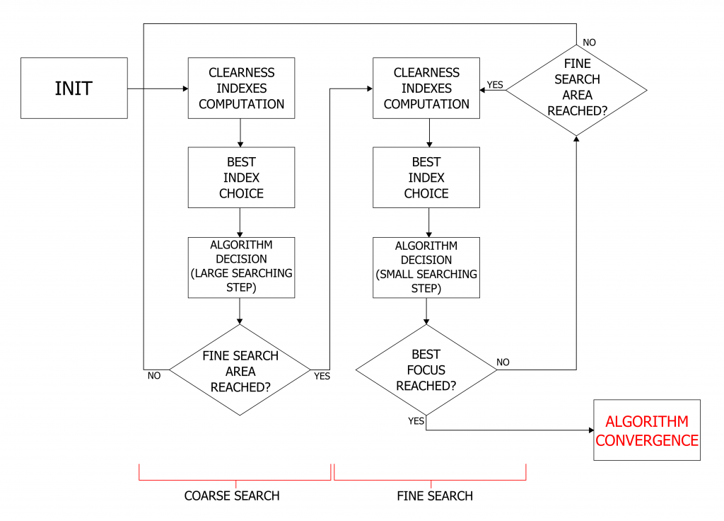
We developed a new system for biomedical macro applications. It uses a liquid lens objective, which implements a voltage control of the focal length, and an autofocus algorithm. The algorithm finds the best focus position using a two-stage search: a coarse searching and a fine searching. This approach combines high accuracy and high speed of convergence.
Figure 1 - Scheme of the autofocus algorithm.
The control variable of the algorithm is the clearness of the acquired image. Various indexes of clearness have been studied to implement the algorithm. Among these, two indexes have been selected, based on the absolute and on the squared values of the image derivatives respectively [2].
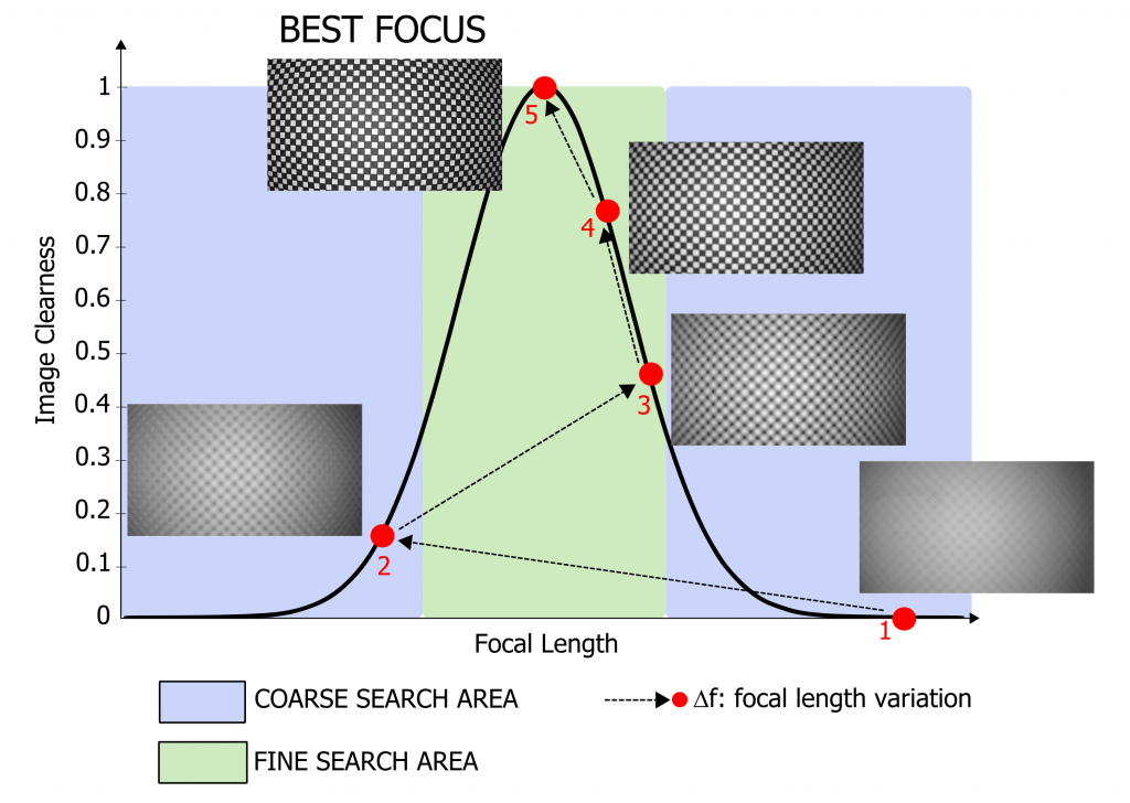
The black curve in figure 2 is the image clearness within the focal length range. The blue and the green areas represent the range in which the algorithm performs a coarse search and a fine search respectively. The red dots correspond to the values of clearness at different focal lengths, at each iteration of the algorithm. As a first step, a coarse search of the best focus position is carried out by varying the focal length from point (1) to subsequent points, until the green region is reached: in the figure, this process is performed in two steps, from point (1) to point (3). Then, the fine search is carried out: here, small increments of the focal length are considered, and the corresponding values of clearness are computed. A suitable threshold based algorithm is used to evaluate both the sign and the entity of the corresponding variations, and to choose the correct convergence direction. In the figure, this process is schematically represented by the path from point (3) to point (5), which corresponds to the best focus position.
Figure 2 - Algorithm approach using a template image.
The algorithm shows good performances in terms of speed of execution and accuracy and exhibits good results in real macro applications such as fingerprints, retinal and melanomas analysis. The algorithm has a good focus stability also with hand-held systems.
The objective of this research activity is to analyze and model the behavior of ReWalk™exoskeletons during SCI patients training.
Powered exoskeletons can be used by persons with complete spinal cord injury (SCI) to achieve bipedal locomotion. The training required before being able to efficiently operate these orthotics, however, is currently based on subjective assessments of the patient performance by his therapist, without any quantitative information about internal loads or assistance level. To solve this issue, a sensor system was developed, combining traditional gait analysis systems such as ground reaction force (GRF) platforms and motion capture systems, with instrumented Lofstrand crutches, created by our team.
To each crutch three strain-gauge bridges were applied, to measure both axial and shear forces, as well as conditioning circuits with transmission modules, a tri-axial accelerometer, and a power management circuit with two batteries. Data are transmitted wirelessly via Bluetooth to a personal computer, and every care was taken to avoid interfering with the user’s gait.
An inverse dynamics analysis, on a simplified biomechanical model of the subject wearing the exoskeleton, is then used to assess both the internal forces acting on shoulders, elbows and neck of the subject, as well as the loads acting on joints. The same analysis was also used to quantify the assistance provided to the user during walking, in terms of vertical forces applied by the therapist to the exoskeleton.
These information could be used to teach orthopedic patients to correctly use these supports and minimize problems connected to their usage, making easier for SCI patients to adopt these devices, and increasing their quality of life, while reducing the costs sustained by the community.