Test day: Motion Capture – TRAP-Lab

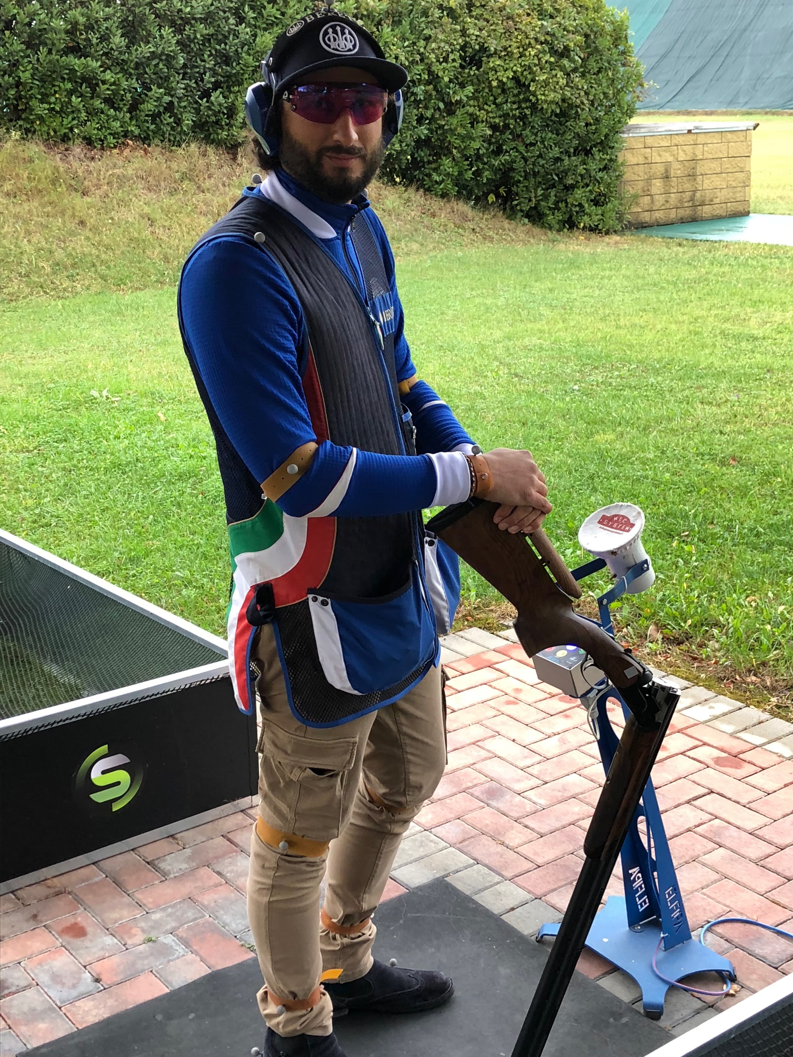
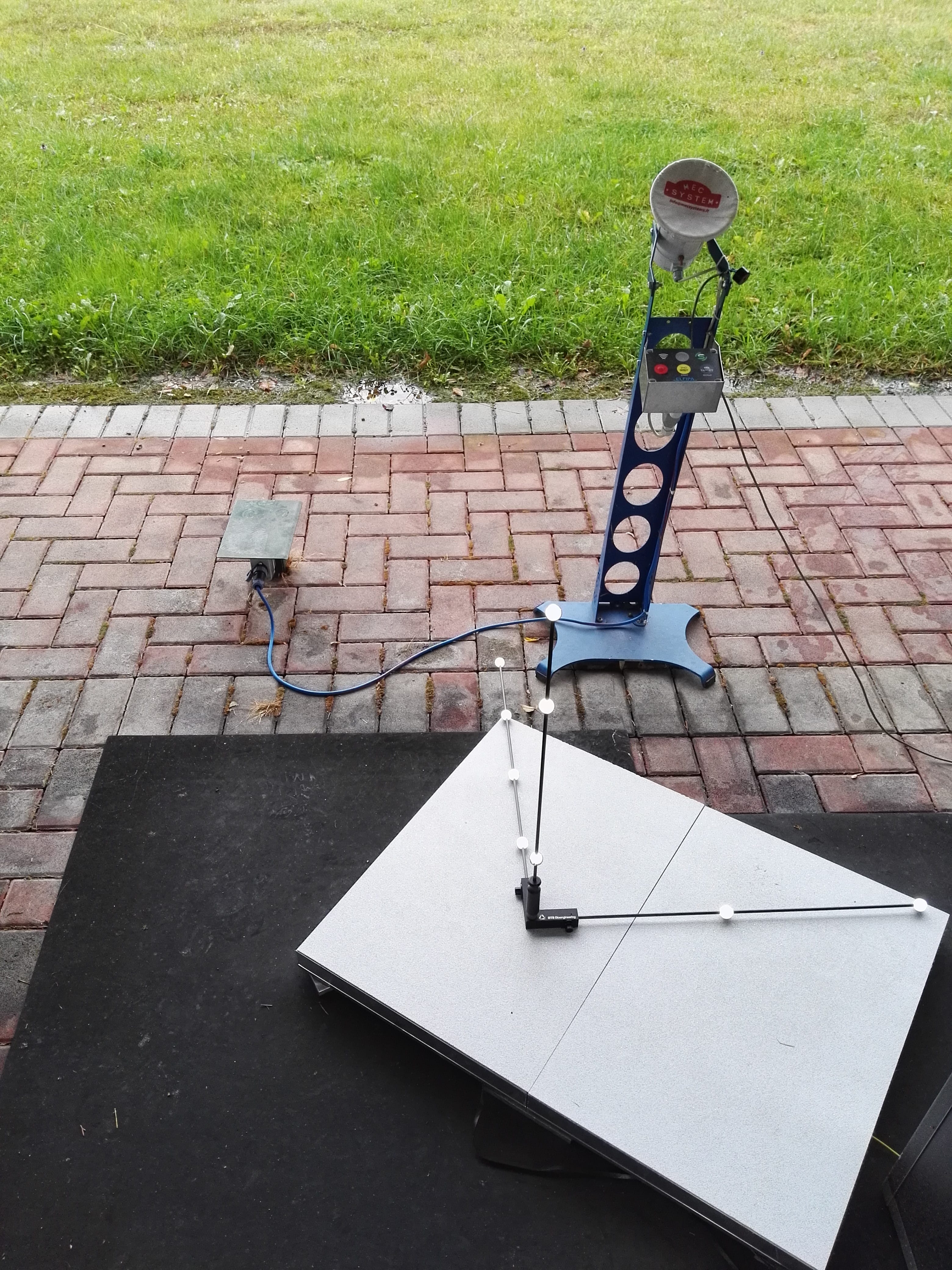
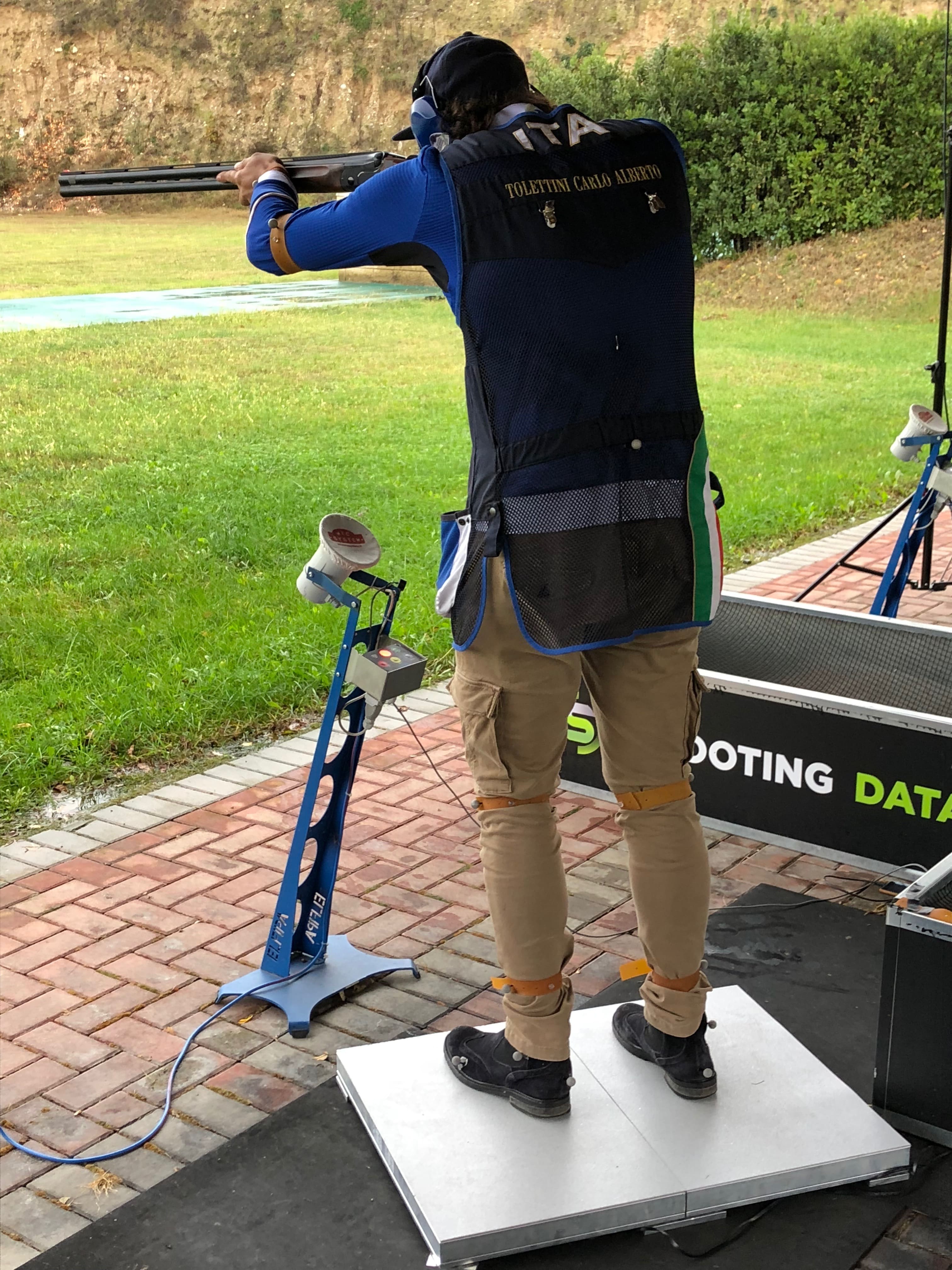
Despite the uncertain weather conditions, the TRAP-Lab and BRaIN teams had an intense day of testing. The new motion capture system, installed experimentally at the TRAP CONCAVERDE field in Lonato del Garda, allows to measure the kinematics and dynamics of the athlete, both before and during the shooting action. The exploratory test will allow to evaluate the system’s reliability and the measurements’ accuracy.

Good results on Rolling Contact

This month we presented our work on Machine Learning used to assess Rolling Contact Fatigue damage progression in two different conference: IMEKO International Metrology Confederation) and ISMA (International Noise and Vibration Engineering Conference).

At the IMEKO in Belfast we presented the results of our project focused on vibrations as a tool to characterize materials.

At the ISMA in Leuven we introduced the preliminary results of the addition of an high-speed camera to our measurement system, to monitor in real-time the specimen surface.

For more information on this project: matteo.lancini@unibs.it

Students now at the UPMC in Paris

First Semester is now starting in Brescia, but some of our master students are currently in Paris for their exchange semester at the University Pierre et Marie Curie.

Good luck and good work to all: have fun, but also make new experiences and develop skills to take back to your work in our lab!

Featured Video Play Icon

First hand experience

In the first year of master at “rehabilitation” course in human science motion of Groningen University students are invited to experience directly the tools that are going to be key of their studies, in a funny and at the same time pragmatic way, to understand the difficulties that occur to people who use these tools daily, also in sports.

Our students Paolo and Ridi, working there, had the pleasure to participate and understand this context in a conscientious and recreative way.

First hand experience on what you are working on is important: every time you design a measurement system it’s best to understand deeply the subject beforehand.

The Lab at EMVA 2018

The Laboratory staff and the Students currently involved in Thesis Projects with us participated at the 2018 European Machine Vision Forum held in Bologna from the 5th to the 7th of September 2018. The theme of this edition was “Vision for Industry 4.0 and beyond“.

Below you can find the two posters that have been presented at the conference.

Wheelchair ergometer @ Groningen

We are working side by side with Groningen University to validate a new ergometer for persons and athletes in wheelchairs.

The device was developed by Groningen University and Lode: Servo engines, together with a load cell run on a feedback loop with a biomechanical model to reproduce overground behaviour.

MMTLab is involved with two of our master students, Paolo and Ridi, to design the calibration setup to validate the ergometer and understand its measurement accuracy in different conditions.

http://www.rug.nl/news-and-events/news/archief2016/nieuwsberichten/0518-unifocusvegter

Marcello is testing the crutches feedback system with David from CAJAL Institute in Madrid

Collaboration with CSIC started this summer

During the summer our staff, including our Bachelor Student Marcello, went to Madrid, to work at a joint project on exoskeleton evaluation with the Cajal Institute. Here you can find some photos of our preliminary tests: more info on the project will be posted in the next days.

Vision and safety for collaborative robotics

The communication and collaboration between humans and robots is one of main principles of the fourth industrial revolution (Industry 4.0). In the next years, robots and humans will become co-workers, sharing the same working space and helping each other. A robot intended for collaboration with humans has to be equipped with safety components, which are different from the standard ones (cages, laser scans, etc.).

In this project, a safety system for applications of human-robot collaboration has been developed. The system is able to:

  • recognize and track the robot;
  • recognize and track the human operator;
  • measure the distance between them;
  • discriminate between safe and unsafe situations.

The safety system is based on two Microsoft Kinect v2 Time-Of-Flight (TOF) cameras. Each TOF camera measures the 3D position of each point in the scene evaluating the time-of-flight of a light signal emitted by the camera and reflected by each point. The cameras are placed on the safety cage of a robotic cell (Figure 1) so that the respective field of view covers the entire robotic working space. The 3D point clouds acquired by the TOF cameras are aligned with respect to a common reference system using a suitable calibration procedure [1].

Figure 1 - Positions of the TOF cameras on the robotic cell.

The robot and human detections are developed analyzing the RGB-D images (Figure 2) acquired by the cameras. These images contain both the RGB information and the depth information of each point in the scene.

Figure 2 - RGB-D images captured by the two TOF cameras.

The robot recognition and tracking (Figure 3) is based on a KLT (Kanade-Lucas-Tomasi) algorithm, using the RGB data to detect the moving elements in a sequence of images [2]. The algorithm analyzes the RGB-D images and finds feature points such as edges and corners (see the green crosses in figure 3). The 3D position of the robot (represented by the red triangle in figure 3) is finally computed by averaging the 3D positions of feature points.

Figure 3 - Robot recognition and tracking.

The human recognition and tracking (figure 4) is based on the HOG (Histogram of Oriented Gradient) algorithm [3]. The algorithm computes the 3D human position analyzing the gradient orientations of portions of RGB-D images and using them in a trained support vector machine (SVM). The human operator is framed in a yellow box after being detected, and his 3D center of mass is computed (see the red square in figure 4).

Figure 4 - Human recognition and tracking.

Three different safety strategies have been developed. The first strategy is based on the definition of suitable comfort zones of both the human operator and the robotic device. The second strategy implements virtual barriers separating the robot from the operator. The third strategy is based on the combined use of the comfort zones and of the virtual barriers.

In the first strategy, a sphere and a cylinder are defined around the robot and the human respectively, and the distance between them is computed. Three different situations may occur (figure 5):

  1. Safe situation (figure 5.a): the distance is higher than zero and the sphere and the cylinder are far from each other;
  2. Warning situation (figure 5.b): the distance decreases toward zero and sphere and cylinder are very close;
  3. Unsafe situation (figure 5.c): the distance is negative and sphere and cylinder collide.
Figure 5 - Monitored situations in the comfort zones strategy. Safe situation (a), warning situation (b), and unsafe situation (c).

In the second strategy, two virtual barriers are defined (Figure 6). The former (displayed in green in figure 6) defines the limit between the safe zone (i.e. the zone where the human can move safely and the robot can not hit him) and the warning zone (i.e. the zone where the contact between human and robot can happen). The second barrier (displayed in red in figure 6) defines the limit between the warning zone and the error zone (i.e. the zone where the robot works and can easily hit the operator).

Figure 6 - Virtual barriers defined in the second strategy.

The third strategy is a combination of comfort zones and virtual barriers (figure 7). This strategy gives redundant information: both the human-robot distance and positions are considered.

Figure 7 - Redundant safety strategy: combination of comfort zones and virtual barriers.

Conclusions

 The safety system shows good performances:
  • The robotic device is always recognized;
  • The human operator is recognized when he moves frontally with respect to the TOF cameras. The human recognition must be improved (for example increasing the number of TOF cameras) in case the human operator moves transversally with respect to the TOF cameras;
  • The safety situations are always identified correctly. The algorithm classifies the safety situations with an average delay of 0.86 ± 0.63s (k=1). This can be improved using a real time hardware.

Related Publications

Pasinetti, S.; Nuzzi, C.; Lancini, M.; Sansoni, G.; Docchio, F.; Fornaser, A. “Development and characterization of a Safety System for Robotic Cells based on Multiple Time of Flight (TOF) cameras and Point Cloud Analysis“, Workshop on Metrology for Industry 4.0 and IoT, pp. 1-6. 2018